8 MC6 User Manual – Part 1, Introduction
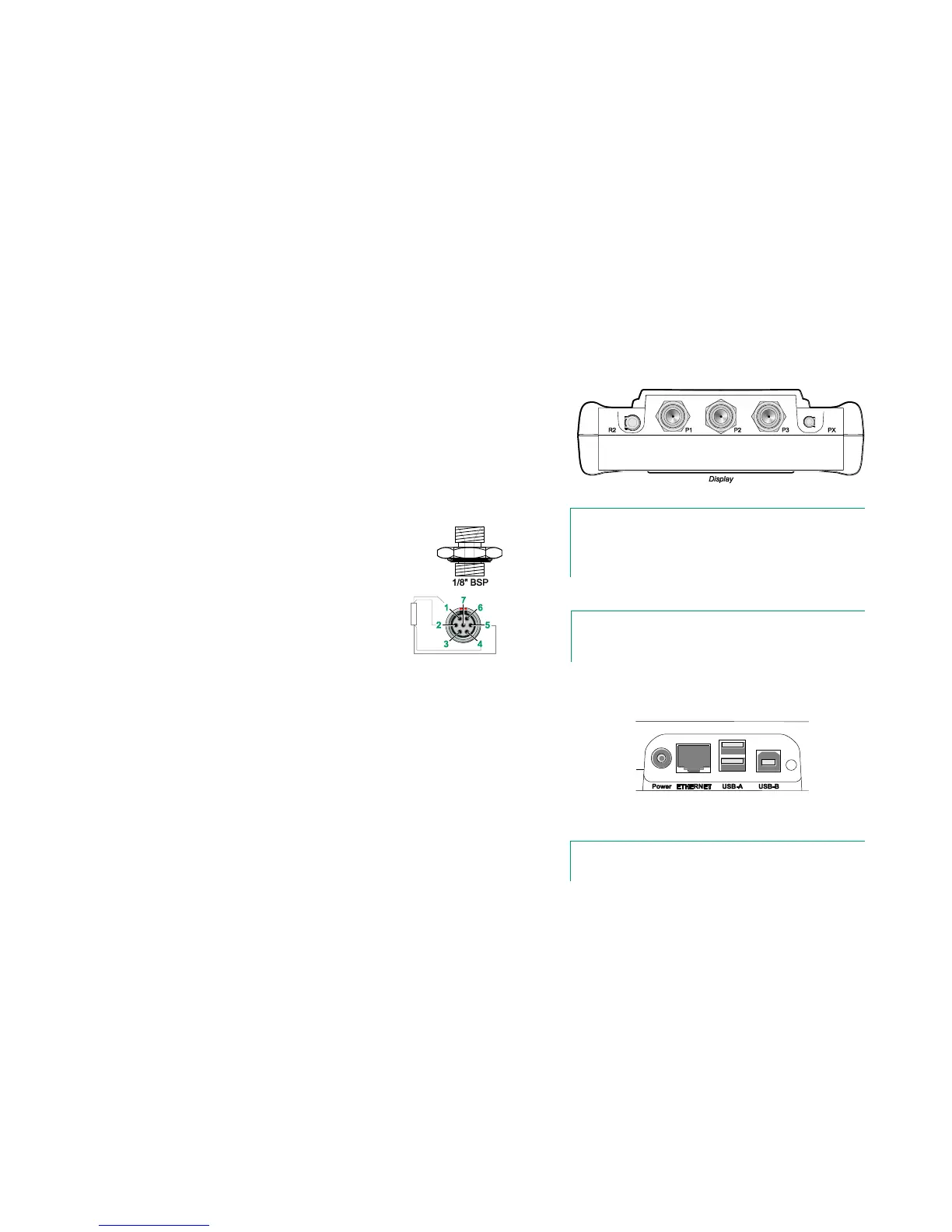
CONNECTORS ON TOP OF MC6
Items from left to right:
R2. A possibility to connect an external RTD sensor to MC6. See also
Hardware Modules/Options and Accessories on page 14.
P1 to P3. Internal Gauge Pressure Module connectors. These are op-
tional. You may have zero to three Internal Gauge Pressure Modules on
your MC6. See also note to the right and chapter Internal Barometric
Pressure Module on page 9.
PX. A possibility to connect Beamex External Pressure Modules to MC6.
MC6, top view.
Note.
If the top view of your MC6 is different, you have the flatter
back side installed. Then your MC6 does not have any internal
pressure modules, except possibly a barometric module.
If you use other pressure hoses than the one delivered by
Beamex, remove the connector meant for Beamex's pressure
hoses and replace them with your own connectors. The thread
available in a Pressure Module's body is 1/8" BSP.
R2 connector's pin order:
Outside view of the female
connector in MC6.
1 Excitation current +
2 Sense +
4 Sense -
5 Excitation current -
Note.
Leave pins 3, 6 and 7 unconnected in the male connector
meant for MC6's R2 connector.
CONNECTORS ON THE RIGHT SIDE OF MC6
The Connectors on the right side of MC6 are:
Power for charging the calibrator. More in chapter About the Charger
and the Charging Procedure on page 10.
Ethernet connector for connecting MC6 to a Local Area Network. This is
a future expansion.
Two USB-A connectors for connecting USB devices to MC6. See also
chapter Firmware Update in the Appendix.
USB-B connector for communicating with a Personal Computer. For de-
tails concerning communication, see PC Communication / Calibration
Software on page 12.
Connectors on the right side of MC6
Note.
All USB connectors are USB 2.0 Full Speed ports