26 MC6 User Manual – Part 2, Active Terminals and Connections
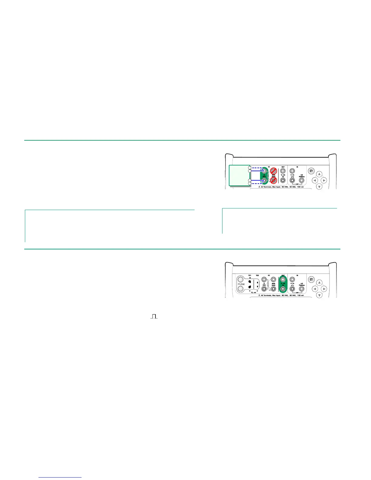
RESISTANCE SIMULATION
Use of 2-, 3- or 4-wire connection is up to the receiving instrument. Connect the
possible third and fourth wire according to the requirements of the connected
instrument, but use only the two leftmost RTD1 terminals in MC6. See adja-
cent picture.
MC6 monitors the resistance measurement current. If the current is too high,
MC6 cannot simulate the right resistance value and displays an error message.
See also: Resistance Measurement on page 20 and
RTD Sensor Simulation on page 25.
Notes.
When simulating resistance or an RTD sensor, using R1 port, MC6 does not support measur-
ing the simulated signal using R2 port.
To ensure good contact between the device under test and the test leads, we recommend us-
ing the alligator clips provided with MC6.
Resistance simulation terminals.
Range 0 … 4000 ohm
Notes.
AC measurement current from the instrument under test is not
supported. With pulsed measurement current, set a wait time
of few milliseconds before the resistance is measured.
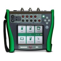
Before generating frequencies, the following settings should be checked:
Amplitude. Defined from the button with the "V" value.
Waveform and Duty Cycle. Set together from the rightmost button.
Duty Cycle is the ratio of the output high time to the total cycle time. Due to
technical reasons, the entered Duty Cycle is not always realized with relatively
high frequencies. When the realized Duty Cycle differs from the desired Duty
Cycle, the realized Duty Cycle is shown with an asterisk (
*
) in front of it, e.g.:
*
8 %
See also: Frequency Measurement on page 20 and
Pulse Generation on page 27.
Frequency generation terminals.
Range 0.0005 … 50000 Hz
Instrument
receiving
simulation
signal