24 MC6 User Manual – Part 2, Active Terminals and Connections
CURRENT GENERATION (SOURCE OR SINK)
MC6's current generation can be done using one of two available methods:
MC6 provides a 24 volt loop supply voltage (source mode).
Setting: Supply: On.
An external device provides the loop supply voltage (sink mode)
Setting: Supply: Off.
Connection depends on the loop supply setting. See pictures to the right.
See also: Current Measurement on page 18.
Note.
If the connected instrument utilizes digital communication and MC6's 24 volt supply voltage is
in use, the following battery symbol is shown in the user interface of Documenting Calibrator
and Data Logger:
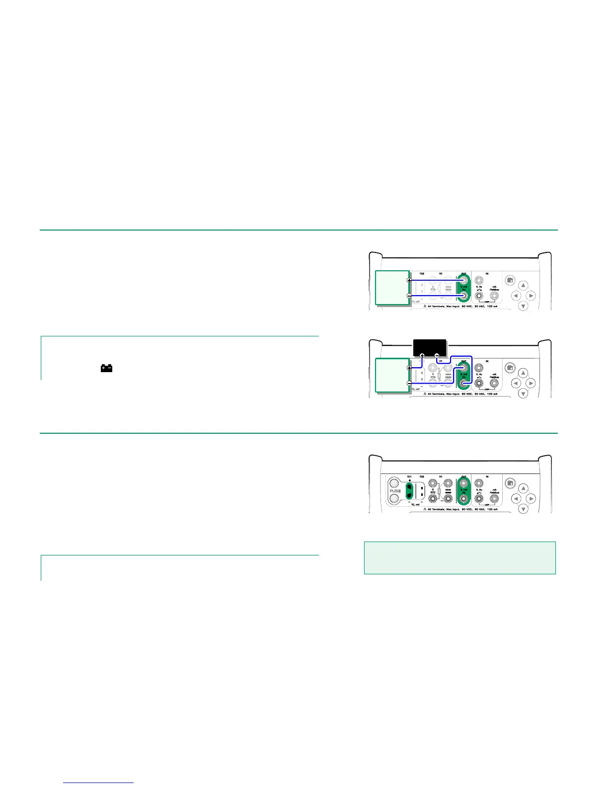
Current generation terminals. Internal supply.
Range 0 … 55 mA
Current generation terminals. External supply
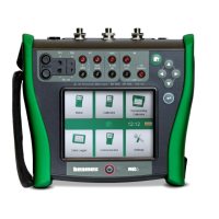
MC6 has two voltage generation terminals. They are listed below (top to bot-
tom) as they are shown in the adjacent picture (left to right):
TC1, generation range: -1 to +1 VDC.
OUT, generation range: -3 to +24 VDC.
Note that you may simulate non-supported thermocouple signals using TC1
port. Since you actually generate (milli)volts, you need a data table to convert
desired temperatures to millivolts.
See also: Voltage Measurement on page 18 and
Thermocouple Simulation on page 25.
Note.
It is advisable to enter 0 V output before connecting the circuit.
Voltage generation terminals.
For ranges, see chapter to the left.
Warning!
Short circuiting the voltage output may result in damage to
MC6 and/or the connected instrument.
Instrument
receiving
current
signal
External
Power Supply
Instrument
receiving
current
signal