20 MC6 User Manual – Part 2, Active Terminals and Connections
RESISTANCE MEASUREMENT
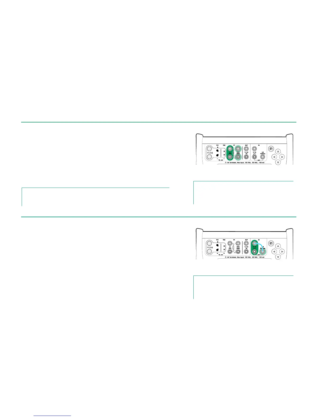
For R1 terminals:
The two leftmost terminals are used in 2-wire systems. MC6 automatically
checks the connection and displays the found wiring system (2-wire, 3-wire or
4-wire).
For R2 terminal:
Beamex offers, as an option, an adapter for the R2 terminal. Please contact
Beamex for details. R2 terminal always uses 4-wire measurement.
See also: Resistance Simulation on page 26 and
Temperature Measurement (RTD) on page 19.
Note.
To ensure good contact between the device under test and the test leads, we recommend us-
ing the alligator clips provided with MC6.
Resistance measurement terminals.
Range -1 … 4040 ohm
Note.
If you get "+OVER" or “-OVER” error messages, check the
connections. If necessary, use 2-wire ohm measurement to
check the wiring.
In frequency measurement, be sure you select a suitable trigger level setting.
To do it, tap on the button with the arrow pointing on a rising ramp and the cur-
rent trigger level voltage. From the opened pop-up window: Select a suitable
trigger level.
See also: Frequency Generation on page 26,
Pulse Counting on page 21 and
Switch Sensing on page 21
Frequency measurement terminals.
Range 0.0027 … 51000 Hz
Note.
There is a trigger level choice for (dry) contacts with no exter-
nal potential. 24V supply may also be used. Connect as light
blue line shows in picture above.