2-2 ASSEMBLY AND STAND OPERATION Biodex Medical Systems, Inc. © 2014
Assembly
Tools Required:
• Knife
• Medium Phillips screwdriver
• Adjustable wrench
Assembly Procedure
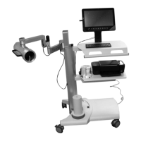
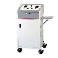
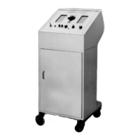
1. Remove the uptake stand from its shipping box and place it in an area suitable for assembly
and setup. Move the arm of the unit out from under the shelf to allow full access.
2. Ensure that power to the uptake stand remains off for the entire following procedure.
3. Take the touch screen display out of its box and place it face down.
4. Take the adjustable height display stand out of its box and connect it to the back of the
touch screen display. The connectors go toward the bottom of the display when mounted.
5. Take the monitor stand and mount it into the holes in the top surface of the upper shelf and
fasten securely from under the top shelf with the four nuts provided.
NOTE: The monitor normally will be mounted so that the uptake arm is to the left of the
operator. This puts the stand to the left of the operator. If the stand needs to be to the right
of the operator, the stand needs to be mounted on the opposite side of the upper shelf.
NOTE: If the update arm is mounted to the operator’s right then you must move the printer
wires. Take a Phillips screwdriver and remove the four screws under the sides of the printer
shelf (middle shelf). The shelf now lifts off. Move the two wires from the slot they are in to
the slot on the other side of the shelf support arm. Put the shelf back on and reinstall the
screws. This is necessary to have enough cable length for the printer.
NOTE: The wires that come up thru the upper shelf must be moved to come thru the holes
next to the moved monitor arm.
6. The stand comes pre-wired and the touch screen display needs to have the connectors for
power and the detectors connected into the computer. The connector for the collimator and
the well are USB connectors that go into the USB ports on the backside of the display.
7. There is a keyboard that needs to be unpacked and placed on the upper shelf.
8. The printer should be placed on the middle shelf and connected to the pre-installed wires
for the signal and power. The other end of the power cable is already connected to the
power strip at the bottom of the stand. The power switch is located on the bottom shelf
near the upright column.
9. If you have purchased a well counter, place it on the side of the uptake stand toward the
operator. This will make it easy to place the wipes or samples into the well counter.
10. The collimator is pre-wired for the uptake arm. If using a well counter, connect the power
and signal cables to the well counter. The cables are in the column.
The Atomlab 960 is now fully set up and ready for operation.
HP Printer Setup (included with system)
Upon power up, you will find that the system defaults to the Microsoft XPS document writer. To
set the HP Printer as your default, view the Windows menu and select the model that is
connected to the system as the default. You will be following the standard Windows format for
setting a device as the default printer.