72 S850 Operation & Maintenance Manual
HYDRAULIC CONTROLS (CONT’D)
High-Flow Hydraulics Operation
This machine may be equipped with High-Flow
Hydr
aulics.
The High-Flow function provides ad
ditional hydraulic fluid
flow to the system to operate an attachment that requires
more hydraulic flow. (EXAMPLE: High-Flow Planer)
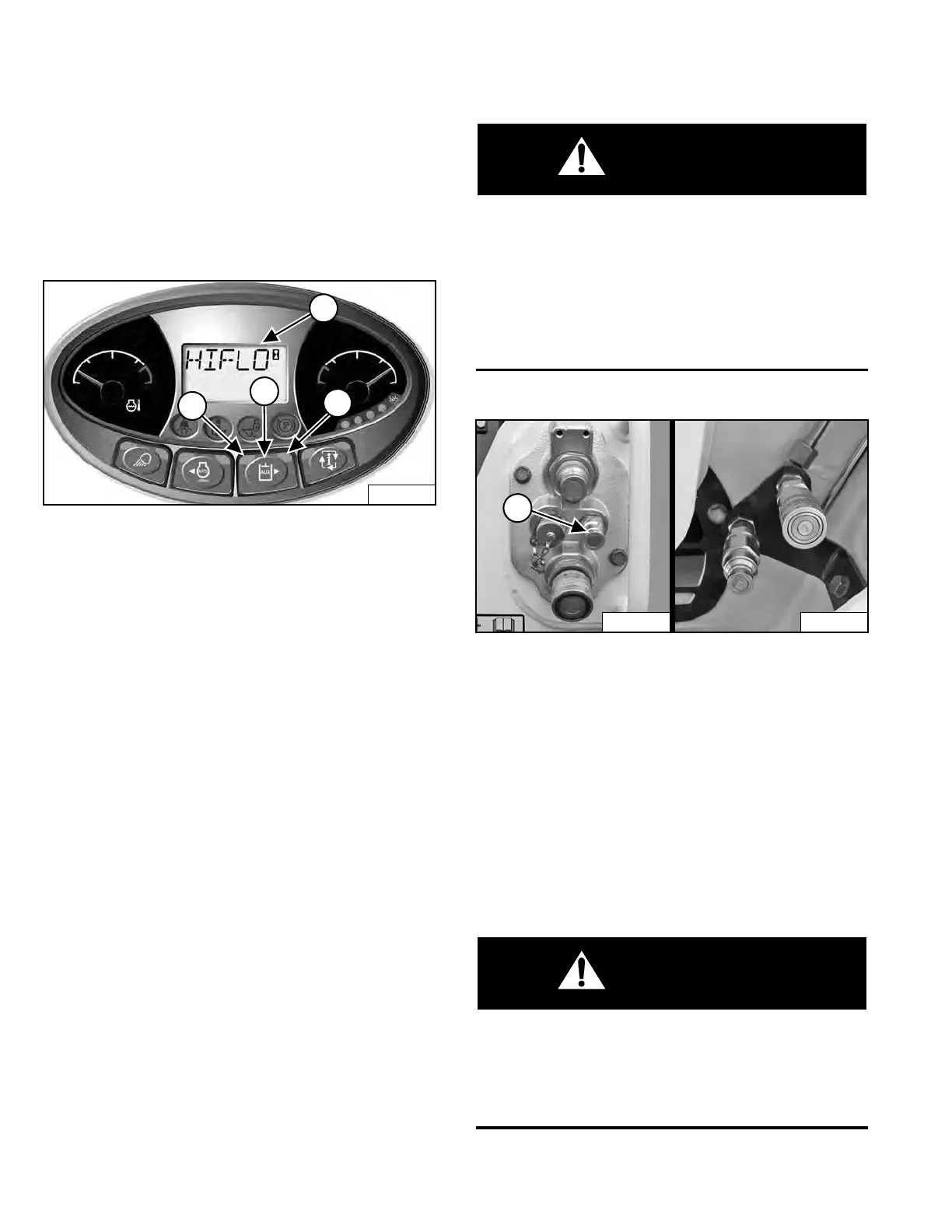
Figure 88
Press the Auxiliary Hydraulics b
utton (Item 2) once to
activate the auxiliary hydraulics. The light (Item 1)
[Figure 88] is ON.
Press the Auxiliary Hydraulics b
utton (Item 2) a second
time to activate high-flow auxiliary hydraulics. Both lights
(Items 1 and 3) are ON. [HIFLO] (Item 4) [Figure 88] will
appear briefly in the data display.
Press the Auxiliary Hydraulics button (Item 2) a third time
to deactiv
ate auxiliary hydraulics. Both lights (Items 1 and
3) [Figure 88] are OFF.
Attachments That Automatically Enable High-Flow
Hydraulics:
Press button once to activate auxiliary hydraulics and
high-flow, both lights are ON; second button press will
deactivate high-flow hydraulics, right light is OFF;
third button press will deactivate auxiliary hydraulics,
both lights are OFF.
Attachments That Automatically Disable High-Flow
Hydraulics:
Press button once to activate auxiliary hydraulics, left
light is ON; second button press will not activate high-
flow hydraulics, right light is ON briefly and turns OFF;
third button press will deactivate auxiliary hydraulics,
both lights are OFF.
NOTE: See attachment Operation & Maintenance
Manual for more information.
Quick Couplers
AVOID INJURY OR DEATH
Diesel fuel or hydraulic fluid under pressure can
penetrate skin or eyes, causing serious injury or
death. Fluid leaks under pressure may not be visible.
Use a piece of cardboard or wood to find leaks. Do
not use your bare hand. Wear safety goggles. If fluid
enters skin or eyes, get immediate medical attention
from a physician familiar with this injury.
W-2072-0807
Figure 89
To Connect: Remove dirt or debris from the surface of the
male and female couplers, and from the outside diameter
of the male couplers. Visually check the couplers for
corroding, cracking, damage, or excessive wear. If any of
these conditions exist, the coupler(s) [Figure 89] must
be replaced.
Install the male couplers into the f
emale couplers. Full
connection is made when the ball release sleeves slide
forward on the female couplers. Some attachments may
have a case drain that needs to be connected to the
small quick coupler (Item 1) [Figure 89].
To Disconnect: Hold the male
couplers. Retract the
sleeves on the female couplers until couplers disconnect.
AVOID BURNS
Hydraulic fluid, tubes, fittings and quick couplers
can get hot when running machine and attachments.
Be careful when connecting and disconnecting quick
couplers.
W-2220-0396
Dealer Copy -- Not for Resale