135 S850 Operation & Maintenance Manual
ELECTRICAL SYSTEM
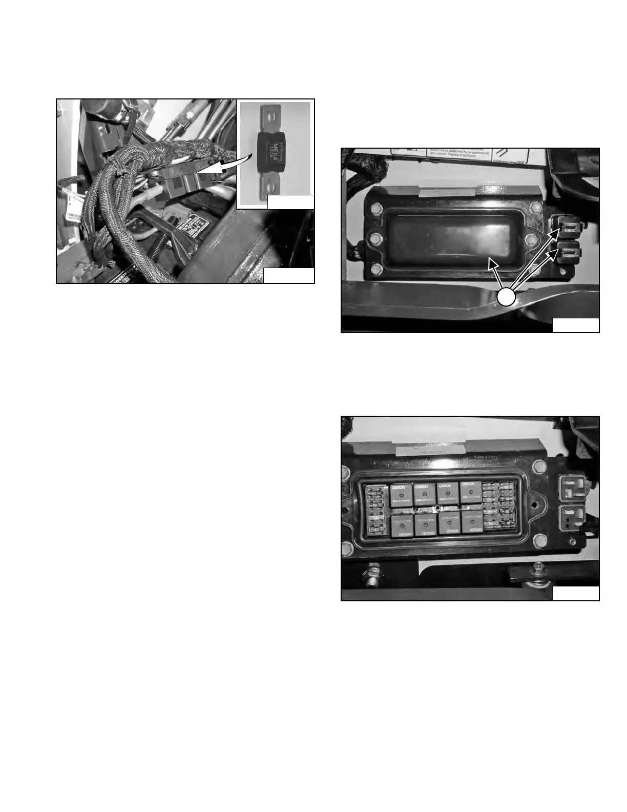
Description
Figure 215
The loader has a 12 volt, negative ground, alternator
charging sy
stem.
The electrical system is protected by fuses located in the
o
perator cab (located under the operator cab in earlier
models) and a 100 ampere master fuse [Figure 215]
located above the battery in the engine compartment.
The fuses will protect the electrical sys
tem when there is
an electrical overload. The reason for the overload must
be found before starting the engine again.
Fuse And Relay Location / Identification
Ear
lier Models
Raise the operator cab. (See Raising on Page 113.)
Figure 216
The electrical system is protected from overload by fuses
an
d relays located under three fuse panel covers (Item 1)
[Figure 216].
Figure 217
Remove the covers to check or replace the fuses
[Figure 217].
A decal is located inside the large cover to show location
an
d amperage ratings.
A table is provided with details on amperage ratings and
circuit
s affected by each fuse and relay. (See Figure 221
on Page 137.)
Dealer Copy -- Not for Resale