Rig Up and Rig Down
Canrig Drilling Technology Ltd. 4-5
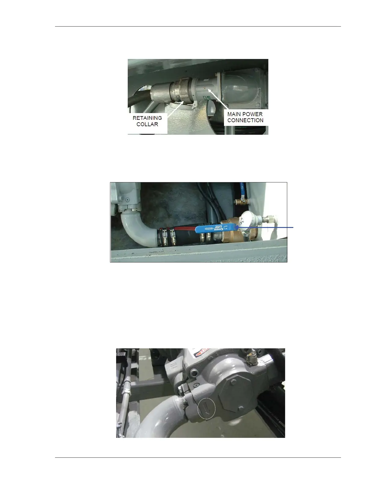
7. Connect the main power cord to the main power connection, Drillers Side at ramp end (Figure 4-5).
Figure 4-5: Main Power Connection
8. Ensure the pump suction valve at the hydraulic tank is open. The pump suction valve lever should be
in line with the suction hose (Figure 4-6).
Figure 4-6: Pump Suction Valve Lever
9. Turn on the main breaker at the master control console. The HMI screen displays the unit status and
the strobe light flashes, indicating an emergency stop error.
10. Check pump rotation during the initial installation and each time wiring changes are made on the rig.
The correct rotation is marked by an arrow on the pump housing (Figure 4-7) located at the suction
port. Remove the coupling guard strip so the coupling can be seen, and start the motor using the Hyd.
Motor HAND/AUTO switch located in the main control box. Consult with an Electrician to correct the
rotation.
Figure 4-7: Pump Rotation Directional Arrow