EasyManua.ls Logo

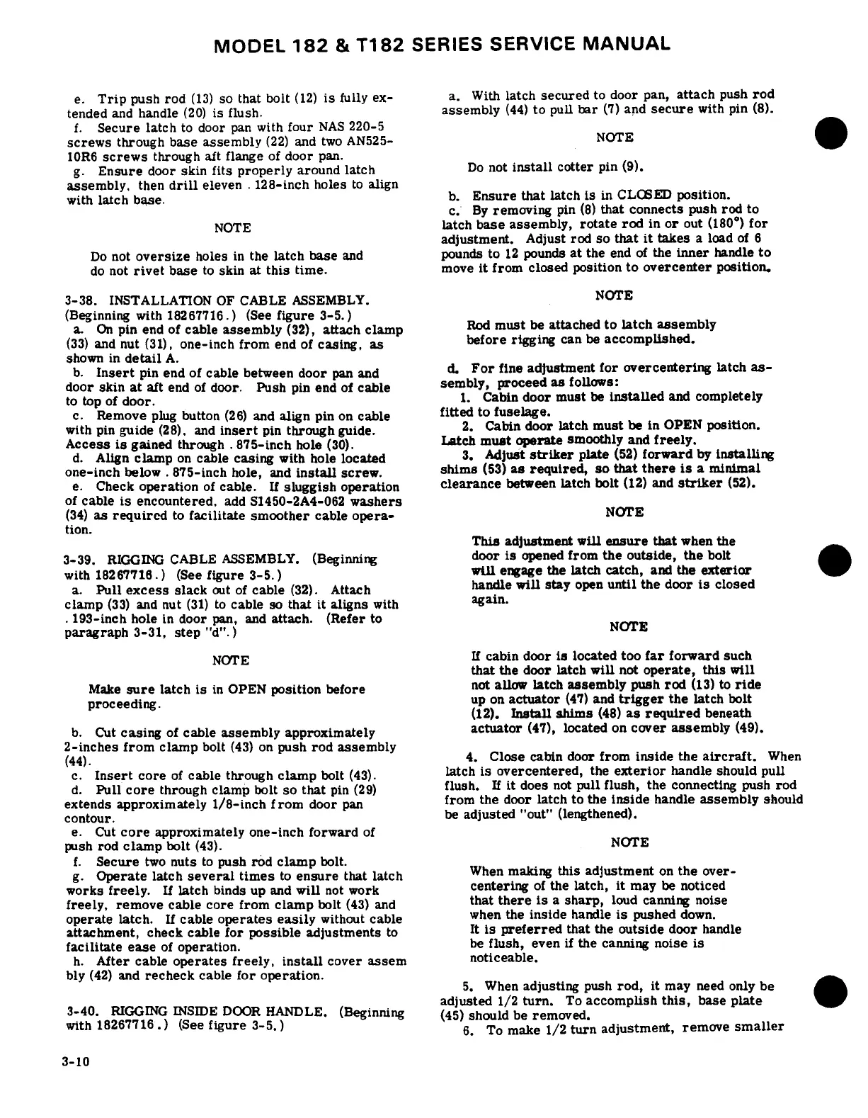
Cessna 182 1978 - Installation of Care Assembly; Rigging Cable Assembly; Rigging Inside Door Handle

Cessna 182 1978
680 pages
Print Icon
To Next Page IconTo Next Page
To Previous Page IconTo Previous Page
Loading...
MODEL
182
&
T182
SERIES
SERVICE
MANUAL
e.
Trip
push
rod
(13)
so
that
bolt
(12)
is
fully
ex-
a.
With
latch
secured
to
door
pan,
attach
push
rod
tended
and
handle
(20)
is flush.
assembly
(44)
to
pull
bar
(7)
and
secure
with
pin
(8).
f.
Secure
latch
to
door
pan
with
four
NAS
220-5
screws
through base
assembly
(22)
and
two AN525-
NOTE
10R6
screws
through
aft flange
of
door
pan.
g.
Ensure
door skin
fits
properly
around
latch
Do
not
install
cotter
pin
(9).
assembly,
then
drill
eleven
.128-inch holes
to
align
with
latch
base.
b.
Ensure
that
latch
is
in
CLOSED
position.
c. By
removing
pin
(8)
that
connects
push
rod
to
NOTE
latch
base
assembly,
rotate rod
in
or
out
(180
°
)
for
adjustment.
Adjust
rod so
that
it
takes
a
load
of
6
Do
not
oversize
holes
in
the
latch
base
and
pounds
to
12
pounds
at
the
end
of
the
inner
handle
to
do
not
rivet
base
to
skin
at
this
time.
move
it
from
closed
position
to
overcenter
position.
3-38.
INSTALLATION
OF
CABLE
ASSEMBLY.
NOTE
(Beginning
with
18267716.)
(See
figure
3-5.)
a.
On
pin
end of
cable
assembly
(32),
attach
clamp
Rod
must
be
attached
to
latch
assembly
(33)
and
nut
(31),
one-inch
from
end
of
casing,
as
before
rigging
can
be
accomplished.
shown
in
detail
A.
b.
Insert
pin
end of
cable
between
door
pan
and
d.
For
fine
adjustment
for
overcentering
latch
as-
door
skin
at
aft
end
of
door.
Push
pin
end
of
cable
sembly,
proceed
as
follows:
to
top
of
door.
1.
Cabin
door
must
be
installed
and
completely
c.
Remove
plug
button
(26)
and
align
pin
on
cable
fitted
to fuselage.
with
pin
guide
(28).
and
insert
pin
through
guide.
2.
Cabin
door
latch
must
be
in
OPEN
position.
Access
is
gained
through
.
875-inch
hole
(30).
Latch
must
operate
smoothly
and
freely.
d.
Align
clamp
on
cable
casing
with
hole
located
3.
Adjust
striker
plate
(52)
forward
by
installing
one-inch
below
.
875-inch
hole,
and
install
screw.
shims
(53)
as required,
so
that
there
is
a
minimal
e.
Check
operation
of
cable.
If
sluggish
operation
clearance
between
latch
bolt
(12)
and
striker
(52).
of
cable
is
encountered,
add
S1450-2A4-062
washers
(34)
as
required
to
facilitate smoother
cable
opera-
NOTE
tion.
This
adjustment
will
ensure
that
when
the
3-39.
RIGGING
CABLE
ASSEMBLY.
(Beginning
door
is
opened
from
the
outside,
the
bolt
with
18267716.)
(See
figure
3-5.)
will
engage
the
latch
catch,
and the
exterior
a.
Pull
excess
slack
out
of
cable
(32).
Attach
handle
will
stay
open
until
the
door
is
closed
clamp
(33)
and
nut
(31)
to
cable
so
that
it
aligns
with
again.
.
193-inch
hole
in
door
pan,
and
attach.
(Refer
to
paragraph
3-31,
step
"d".)
NOTE
NOTE
If
cabin
door
is
located
too
far
forward
such
that
the
door
latch
will
not
operate,
this
will
Make
sure
latch
is
in
OPEN
position
before
not
allow
latch
assembly
push
rod
(13)
to
ride
proceeding.
up
on
actuator
(47)
and
trigger
the
latch
bolt
(12).
Install
shims
(48)
as required
beneath
b.
Cut
casing
of
cable
assembly
approximately
actuator
(47),
located
on
cover
assembly
(49).
2-inches
from
clamp
bolt
(43)
on
push
rod
assembly
(44)
4.
Close
cabin
door
from
inside
the
aircraft.
When
c.
Insert
core
of
cable
through
clamp
bolt
(43).
latch
is
overcentered,
the
exterior
handle
should
pull
d.
Pull
core
through
clamp
bolt
so
that
pin
(29)
flush.
If
it
does
not
pull
flush,
the
connecting
push
rod
extends
approximately
1/8-inch
from
door
pan
from
the
door
latch
to
the
inside
handle
assembly
should
contour.
be
adjusted
"out" (lengthened).
e.
Cut
core
approximately one-inch forward
of
push
rod
clamp
bolt
(43).
NOTE
f.
Secure
two
nuts
to
push
rod
clamp
bolt.
g.
Operate
latch
several
times
to
ensure
that
latch
When
making
this
adjustment
on
the
over-
works
freely.
If
latch
binds up
and
will
not
work
centering
of
the latch,
it
may
be
noticed
freely,
remove
cable
core
from
clamp
bolt
(43)
and
that
there
is
a
sharp,
loud
canning
noise
operate
latch.
If
cable
operates
easily
without
cable
when
the
inside
handle
is
pushed
down.
attachment,
check
cable
for
possible
adjustments
to
It
is
preferred
that
the
outside
door
handle
facilitate
ease
of
operation.
be
flush,
even
if
the
canning
noise
is
h.
After
cable
operates
freely,
install
cover
assem
noticeable.
bly
(42)
and
recheck
cable
for
operation.
5.
When
adjusting
push
rod,
it
may
need
only
be
adjusted
1/2
turn.
To
accomplish
this,
base
plate
3-40.
RIGGING
INSIDE
DOOR
HANDLE.
(Beginning
(45)
should
be
removed.
with
18267716.)
(See
figure
3-5.)
6.
To
make
1/2
turn
adjustment, remove
smaller
3-10

Table of Contents