EasyManua.ls Logo

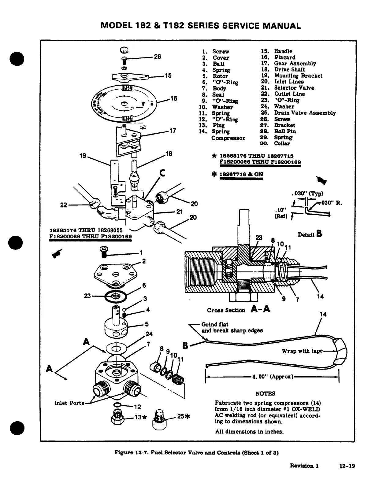
Cessna 182 1978 - Fuel Selector Valve and Controls

Cessna 182 1978
680 pages
Print Icon
To Next Page IconTo Next Page
To Previous Page IconTo Previous Page
Loading...
MODEL
182
&
T182
SERIES
SERVICE
MANUAL
t
<--26
2.
Cover
16.
Placard
7I*y
T
3.
Ball
17.
Gear
Assembly
4.
Spring
18.
Drive
Shaft
· 1
5---15
5.
Rotor
19.
Mounting
Bracket
6.
"O'-Ring
20.
Inlet
Lines
7.
Body
21.
Selector
Valve
0/~.~P^
\
..
8.
Seal
22.
Outlet
Line
f- _
,
s
r
6
9.
"1Y'-1Rng
23.
"O"-Ring
\,k ^ --- '-/
J10.
Washer
24.
Washer
ar,,_+ _~.j~
~
11.
Spring
25.
Drain
Valve
Assembly
12.
"O"-Rlng
26.
Screw
- D
~ I3
13.
Plug
27.
Bracket
.>
17
14.
Spring
88.
Roll
Pin
{-Ssf
^
~
Compressor
29.
Spring
30.
Collar
19_
18
*
18288176
THRU
18267715
_7"--T
r ^F18200026
T
F18200189
} A C
,~*
18287716
& ON
i;;\ r Ef
//^
^
.030"
(Typ)
22---\^ . 200 ll|t
03(0
R.
__a ,<
-21
_
.10"
L /-20
(Ref)
Fl8200026
THRU
F18200169
23Detal
I---
I
oee,#~~~~~~~~~
;
1011
6
23
3
9 7
14
f
>21-4
Cross
Section
A-A
[.)
L.J
°
5
~--Grind
flat
/
I
24"S'^f ~
9^
^and
break
sharp
edges
91011y^^
8
9
Wrap with
tape
NOTES
Inlet
Ports
0-12
Fabricate
two
spring
compressors
(14)
i
^
z
:
1 2
from
1/16
inch
diameter
#1
OX-WELD
j_13*r
.l _
25*
AC
welding
rod
(or
equivalent)
accord-
-*~_.Y /24
d
reing
to dimensions
shown.
All
dimensions
in
inches.
Figure
12-7.
Fuel
Selector
Valve
and
Controls
(Sheet
1
of
3)
Revision
1
12-19

Table of Contents