EasyManua.ls Logo

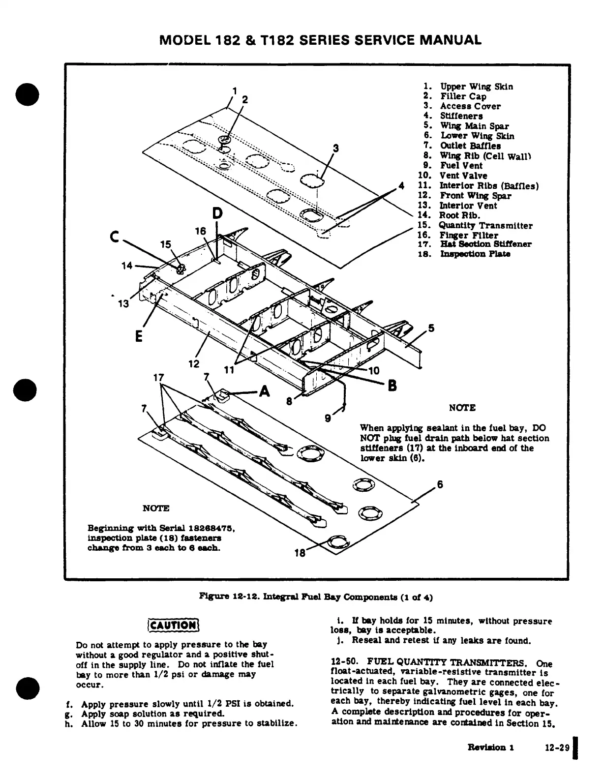
Cessna 182 1978 - Fuel Quantity Transmitters; Integral Fuel Bay Components

Cessna 182 1978
680 pages
Print Icon
To Next Page IconTo Next Page
To Previous Page IconTo Previous Page
Loading...
MODEL
182
&
T182
SERIES
SERVICE
MANUAL
*-~1
1'
t
~1.
Upper
Wing
Skin
I/
2
2.
Filler
Cap
2,J ^^~
/
~3.
Access
Cover
4.
Stiffeners
5.
Wing
Main
Spar
.~"*-
(j. '"4~
%
-
.
6
6.
Lower
Wing
Skin
/*'*C - ''--
\s
3
7.
Outlet
Baffles
wj\ ''--.t ^-q f - \ /
8.
Wing
Rib
(Cell
Wall)
\'^ '-'--_ '-;'
'.-:
."y.,
,,
9.
Fuel
Vent
\ '..
'"::;. ""--
<
10.
Vent
Valve
4
11.
Interior
Ribs
(Bafles)
<:A
:I^.
'".C -
1
12.
Front
Wing
Spar
\'"^
.
"1
J,
_
\
13.
Interior
Vent
D
I:_~ /.s^
14.
Root
Rib.
|ft \y
^^s.
'
k;
;-.,-<--
^15.
Quantity
Transmitter
C \ 9s16_/ .
Finger
Filter
C15K
17.
Hat
Section
Stiffener
^^.
^^<^e-at
Ax^-.
\
s
^
When
applying
sealant
in
the
fuel
bay,
DO
(
Gus$?
t
^\^
^
<
^
~>^
\^
NOT
plug
fuel
drain
path
below
hat
section
Beginning
with
Serial
18288475,
\
/
~~~~~~~~~i.
inspection
plate (18)
fasteners
lat
12
17
7
7chag
fom
3
each
NOTE
'.'
A
i.
"'.>
loss,
bay
is
acceptable.
Do
not
attempt
to apply
pressure
to
the
bay
i.
Reseal
and
retest
if
a
leaks
are
found.
without
a
good
regulator
and
a
positive
shut-
off in thesplie ontinlth ul1-0When
applyinsu sealant
iin
the
fuel
bay,TERS.
One
bay
to
more
than
1/2
psi
or
damage
may
float-actuated,
variable-resistive
transmitter
is
y tomooccur eha 2sodmae
a
located
in
eachp
fuel
drain
path
below
hat
s
connected
onc-
trically
to
separate
galvanometric
gages,
one
for
r
skin
(6).
Apply
pressure
slowly
untl
1/2
PSI
is
obtained
each
tereby
ndicl
82level
n
each
bay.
Apply
soap
solution
as
requition
and
procedur
fteor
oper
change
from
3
each
to
6
each.
Figure
12-12.
Integrai
Fuel
Bay
Components
(1
of
4)
h. Allow
15
to
30
minutes
form
pressure
to
stabilize.
aton
and
mintenance
are
contained
in
Secton
15.
losRevson,
bay
is
accep
ble29
J.
Reseal
and
retest
if
any
leaks
are
found.
without
a
good
regulator
and
a
positive
shut-
off
in
the
supply
line.
Do
not
inflate
the
fuel
12-50.
FUEL
QUANITY
TRANSMITTERS.
One
bay
to
more
than
1/2
psi
or
damage
mary
float-actuated,
variable-resistive
transmitter
is
occur.
located
in
each
fuel
bay.
They
are
connected
elec-
trically
to
separate
galvanometric
gages,
one
for
f.
Apply
pressure
slowly
until
1/2
PSI
is
obtained.
each
bay,
thereby
indicating
fuel level
in
each
bay.
g.
Apply
soap
solution
as
required.
A
complete
description
and
procedures
for
oper-
h.
Allow
15
to
30
minutes
for
pressure
to
stabilize.
ation
and
maintenance
are
contained
in
Section
15.
Revision
I
12-29

Table of Contents