EasyManua.ls Logo

Cessna 182 1978 - Carburetor Heat Control; Mixture Control; Propeller Control; Starting System

Cessna 182 1978
680 pages
Print Icon
To Next Page IconTo Next Page
To Previous Page IconTo Previous Page
Loading...
MODEL
182
&
T182
SERIES
SERVICE
MANUAL
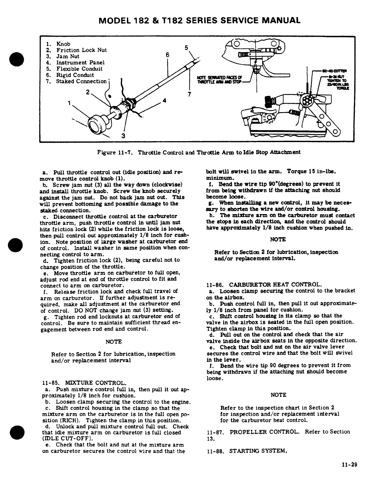
1.
Knob
2.
Friction
Lock
Nut
3.
Jam
Nut
6
4.
Instrument
Panel
5.
Flexible
Conduit
6.
Rigid
Conduit
7.
Staked
Connection
^S1
iO
m
3
Figure
11-7.
Throttle
Control
and
Throttle
Arm
to
Idle
Stop
Attachment
a.
Pull
throttle
control
out
(idle
position)
and
re-
bolt
will
swivel
in
the
arm.
Torque
15
in-lbs.
move
throttle
control
knob
(1).
minimum.
b.
Screw
jam
nut
(3)
all
the
way
down
(clockwise)
f.
Bend
the
wire
tip
90°(degrees)
to
prevent
it
and
install
throttle
knob.
Screw
the
knob
securely
from
being
withdrawn
if
the
attaching
nut
should
against
the
jam
nut.
Do
not
back
jam
nut
out.
This
become
loose.
will
prevent
bottoming
and
possible
damage
to
the
g.
When
installing
a
new
control,
it
may
be
neces-
staked
connection.
sary
to
shorten
the
wire
and/or
control
housing.
c.
Disconnect
throttle
control
at
the
carburetor
h.
The
mixture
arm
on
the
carburetor
must
contact
throttle
arm,
push
throttle
control
in
until
jam
nut
the
stops
in
each
direction,
and
the
control
should
hits
friction
lock
(2)
while
the
friction
lock
is
loose,
have
approximately
1/8
inch
cushion
when
pushed
in.
then
pull
control
out
approximately
1/8
inch
for
cush-
ion.
Note
position
of
large
washer
at
carburetor
end
NOTE
of
control.
Install
washer
in
same
position
when con-
necting
control
to
arm.
Refer
to
Section
2
for
lubrication,
inspection
d.
Tighten
friction
lock
(2),
being
careful
not
to
and/or
replacement
interval.
change
position
of
the
throttle.
e.
Move
throttle
arm
on
carburetor
to
full
open,
adjust
rod
end
at
end
of
throttle
control
to
fit
and
connect
to
arm
on
carburetor.
11-86.
CARBURETOR
HEAT
CONTROL.
f.
Release
friction
lock
and
check
full
travel
of
a.
Loosen
clamp
securing
the
control
to
the
bracket
arm
on
carburetor.
If
further
adjustment
is
re-
on
the
airbox.
quired,
make
all
adjustment
at
the
carburetor
end
b.
Push control
full
in,
then
pull
it
out
approximate-
of
control.
DO
NOT
change
jam
nut
(3)
setting.
ly
1/8
inch
from
panel
for
cushion.
g.
Tighten
rod
end
locknuts
at
carburetor
end
of
c.
Shift
control
housing
in
its
clamp
so
that
the
control.
Be
sure
to
maintain
sufficient
thread
en-
valve
in
the
airbox
is
seated
in
the
full
open
position.
gagement
between
rod
end
and
control.
Tighten
clamp
in
this
position.
d.
Pull
out
on
the
control
and
check
that
the
air
NOTE
valve
inside
the
airbox
seats
in
the
opposite
direction.
e.
Check
that
bolt
and
nut
on
the
air
valve
lever
Refer
to
Section
2
for
lubrication,
inspection
secures
the
control
wire
and
that
the
bolt
will
swivel
and/or
replacement
interval
in
the
lever.
f.
Bend
the
wire
tip
90
degrees
to
prevent
it
from
being
withdrawn
if
the
attaching
nut
should
become
loose.
11-85.
MIXTURE
CONTROL.
a.
Push
mixture
control
full
in,
then pull
it
out
ap-
proximately
1/8
inch
for
cushion.
NOTE
b.
Loosen
clamp
securing
the
control
to
the
engine.
c.
Shift
control
housing in
the
clamp
so
that
the
Refer
to
the
inspection
chart
in
Section
2
mixture
arm
on
the
carburetor
is
in
the full
open
po-
for
inspection
and/or
replacement
interval
sition
(RICH).
Tighten
the clamp
in
this
position.
for
the
carburetor
heat
control.
d.
Unlock
and
pull
mixture
control
full
out.
Check
that
idle
mixture
arm
on
carburetor
is
full
closed
11-87.
PROPELLER
CONTROL.
Refer
to
Section
(IDLE
CUT-OFF).
13.
e.
Check
that the
bolt
and
nut
at
the
mixture
arm
on
carburetor
secures
the
control
wire
and
that
the
11-88.
STARTING
SYSTEM.
11-29

Table of Contents