EasyManua.ls Logo

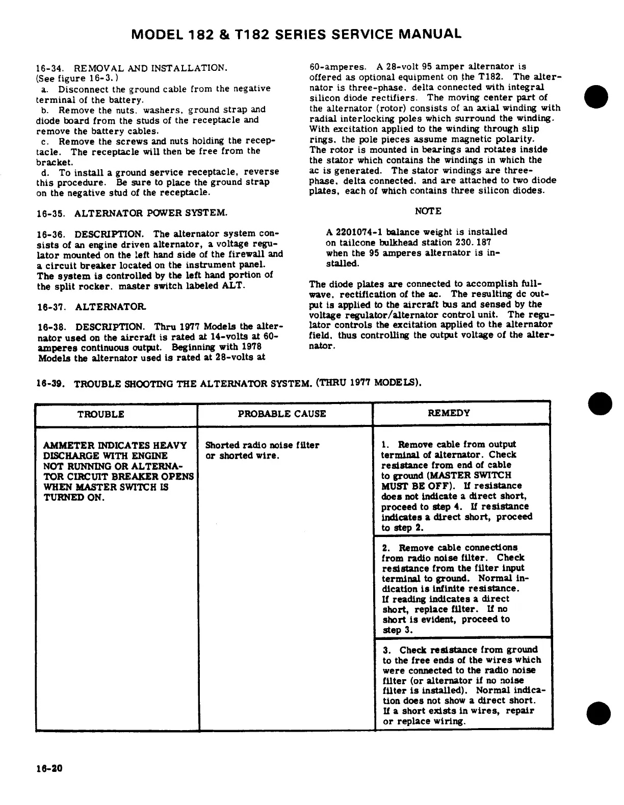
Cessna 182 1978 - Alternator; Alternator Power System; Troubleshooting the Alternator System

Cessna 182 1978
680 pages
Print Icon
To Next Page IconTo Next Page
To Previous Page IconTo Previous Page
Loading...
MODEL
182
&
T182
SERIES
SERVICE
MANUAL
16-34.
REMOVAL
AND
INSTALLATION.
60-amperes.
A
28-volt
95
amper
alternator
is
(See
figure
16-3.)
offered
as
optional
equipment
on
the T182.
The
alter-
a.
Disconnect
the
ground
cable
from
the
negative
nator
is
three-phase.
delta
connected
with
integral
terminal
of
the
battery.
silicon
diode
rectifiers.
The
moving
center
part
of
b.
Remove
the
nuts.
washers,
ground
strap
and
the
alternator
(rotor)
consists
of
an
axial
winding
with
diode
board
from
the
studs
of
the
receptacle
and
radial
interlocking
poles
which
surround
the
winding.
remove
the
battery
cables.
With
excitation
applied
to
the winding
through
slip
c.
Remove
the
screws
and
nuts
holding the
recep-
rings.
the pole
pieces
assume
magnetic
polarity.
tacle.
The
receptacle
will
then
be
free
from
the
The
rotor
is
mounted
in
bearings
and
rotates
inside
bracket.
the
stator
which
contains
the
windings
in
which the
d.
To
install
a
ground
service
receptacle,
reverse
ac
is
generated.
The
stator
windings
are
three-
this
procedure.
Be
sure
to
place
the
ground
strap
phase,
delta
connected.
and
are
attached
to
two
diode
on
the
negative
stud
of
the
receptacle.
plates,
each
of
which
contains
three
silicon
diodes.
16-35.
ALTERNATOR
POWER
SYSTEM.
NOTE
16-36.
DESCRIPTION.
The
alternator
system
con-
A
2201074-1
balance
weight
is
installed
sists
of
an
engine
driven
alternator,
a
voltage
regu-
on
tailcone
bulkhead
station
230.
187
lator
mounted
on
the
left
hand
side
of
the
firewall
and
when
the
95
amperes
alternator
is
in-
a
circuit
breaker
located
on
the
instrument
panel,
stalled.
The
system
is
controlled
by
the
left
hand
portion
of
the
split
rocker.
master
switch
labeled
ALT.
The
diode
plates
are
connected
to
accomplish
full-
wave.
rectification
of
the
ac.
The
resulting
dc
out-
16-37.
ALTERNATOR.
put
is
applied
to
the
aircraft
bus
and
sensed
by
the
voltage
regulator/alternator
control
unit.
The
regu-
16-38.
DESCRIPTION.
Thru
1977
Models
the
alter-
lator controls
the
excitation
applied
to
the
alternator
nator
used
on
the
aircraft
is
rated
at
14-volts
at
60-
field,
thus controlling
the
output
voltage
of
the
alter-
amperes
continuous
output.
Beginning
with
1978
nator.
Models the
alternator
used
is
rated
at
28-volts
at
16-39.
TROUBLE
SHOOTING
THE ALTERNATOR
SYSTEM.
(THRU
1977 MODELS).
TROUBLE PROBABLE
CAUSE
REMEDY
AMMETER
INDICATES
HEAVY
Shorted
radio
noise
filter
1.
Remove
cable
from
output
DISCHARGE
WITH ENGINE
or shorted wire.
terminal
of
alternator.
Check
NOT
RUNNING
OR
ALTERNA-
resistance
from
end
of
cable
TOR
CIRCUIT
BREAKER
OPENS
to
ground
(MASTER
SWITCH
WHEN
MASTER
SWITCH
IS
MUST
BE
OFF).
If
resistance
TURNED
ON.
does
not
indicate
a
direct
short,
proceed
to
step
4.
If
resistance
indicates
a
direct
short, proceed
to
step
2.
2.
Remove
cable
connections
from radio noise
filter.
Check
resistance
from
the
filter
input
terminal
to
ground.
Normal
in-
dication
is
infinite
resistance.
If
reading
indicates
a
direct
short,
replace
filter.
If
no
short
is
evident,
proceed
to
step
3.
3.
Check
resistance
from
ground
to
the
free
ends
of
the
wires
which
were
connected
to
the
radio
noise
filter
(or
alternator
if
no
noise
filter
is
installed).
Normal
indica-
tion
does
not
show
a
direct
short.
If
a
short
exists
in
wires,
repair
or
replace
wiring.
16-20

Table of Contents