EasyManua.ls Logo

Cessna 182 1978 - Elevator Trim Tab Travel Stop Adjustment

Cessna 182 1978
680 pages
Print Icon
To Next Page IconTo Next Page
To Previous Page IconTo Previous Page
Loading...
MODEL
182
&
T182
SERIES
SERVICE
MANUAL
,
FWD
a
1.
With
elevators
in
neutral.
set
trim
tab
to
neutral
(streamlined).
2.
Position
stop
blocks
(2
and
3)
against
cable
ends
and
secure
to
cable
A.
3.
Place
inclinometer
on
trim
tab
and
lower
to
degree
specified
in
figure
1-1.
4.
Position
stop
block
(4)
against
stop
block
(3)
and
secure
to cable
B.
5.
Raise
trim
tab
to
specified
degree.
place
stop
block
(1)
against
stop
block
(2)
and
secure
to
cable
B.
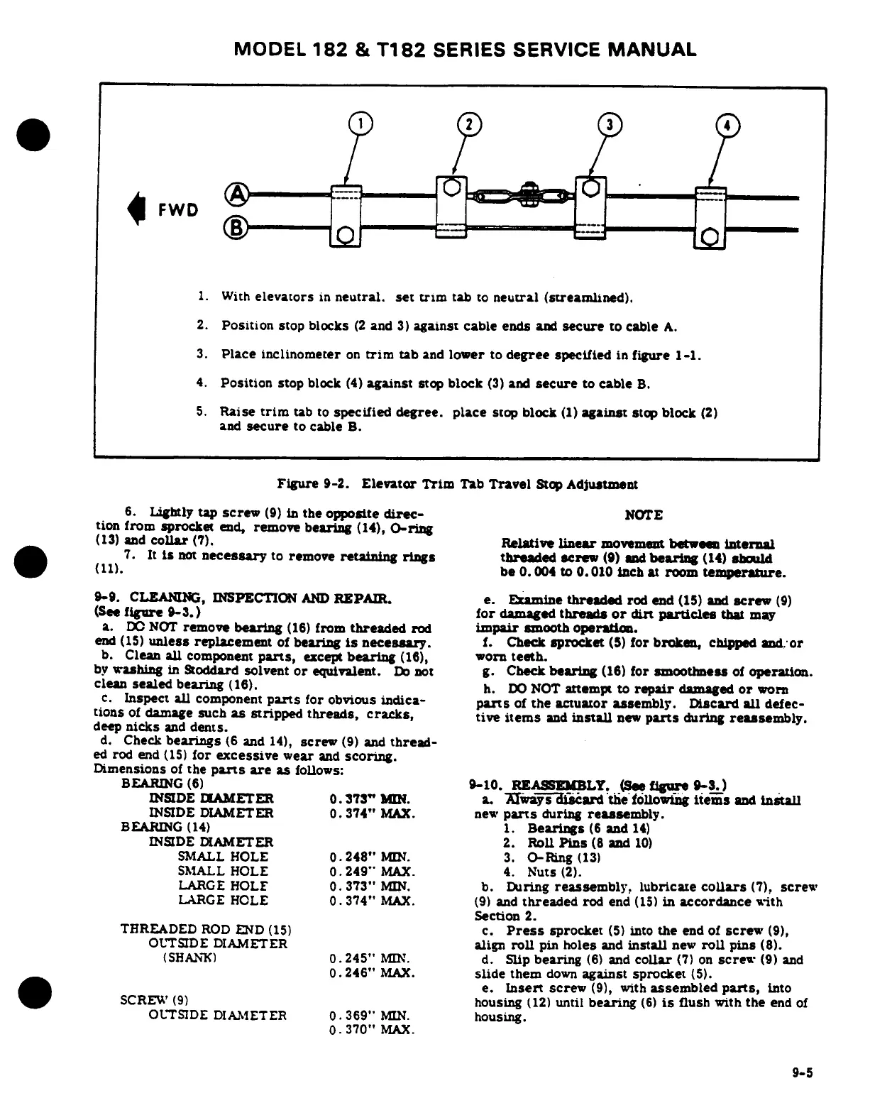
Figure
9-2.
Elevator
Trim
Tab
Travel
Stop
Adjustment
6.
Lightly
tap
screw
(9)
in
the
opposite
direc-
NOTE
tion
from
sprocket
end,
remove
bearing
(14),
O-ring
(13)
and
collar
(7).
Relative
linear
movement
between
Internal
7.
It
is
not
necessary
to
remove
retaining
rings
threaded
screw
(9)
and
bearing
(14)
should
^^
(
~~~~~~11
L
~).
~be
0.004
to
0.010
inch
at
room
temperature.
99.
CLEANING,
INSPECTION
AND
REPAIR.
e.
Examine
threaded
rod
end
(15)
and
screw
(9)
(See
figure
9-3.)
for
damaged
threads
or
dirt
paricles
that
may
a.
DC
NOT
remove
bearing
(16)
from
threaded
rod
impair
smootb
operation.
end
(15)
unless
replacement
of
bearing
is
necessary.
f.
Check
sprocket
(5)
for
broken,
chipped
and.
or
b.
Clean
all
component
parts,
except
bearing
(16),
worn
teeth.
by
washing
in
Soddard
solvent
or
equivalent.
Do
not
g.
Check
bearing
(16)
for
smoothness
of
operation.
clean
sealed
bearing
(16).
h.
DO
NOT
attempt
to
repair
damaged
or
worn
c.
Inspect
all
component
parts
for
obvious
indica-
parts
of
the
actuator
assembly.
Discard
all
defec-
tions
of
damage
such
as
stripped
threads,
cracks,
tive
items
and
install
new
parts
during
reassembly.
deep
nicks
and
dents.
d.
Check
bearings
(6
and
14),
screw
(9)
and
thread-
ed
rod
end
(15)
for
excessive
wear
and
scoring.
Dimensions
of
the
parts
are
as
follows:
BEARING
(6)
9-10.
REASSEMBLY.
(See
figure
9-3.)
INSIDE
IIAMETER
0.373"
MIN.
a.
XwaIfsicard
the
following
items
and
install
INSIDE
DIAMETER
0.
374"
MAX.
new
parts
during
reassembly.
BEARING
(14)
1.
Bearings
(6
and
14)
INSIDE
DIAMETER
2.
Roll
Pins
(8
and
10)
SMALL
HOLE
0.248"
MIN.
3.
O-Ring
(13)
SMALL
HOLE
0.249"
MAX.
4.
Nuts
(2).
LARGE
HOLE
0.
373"
MIN.
b.
During
reassembly,
lubricate
collars
(7),
screw
LARGE
HOLE
0.374"
MAX.
(9)
and
threaded
rod
end
(15)
in
accordance
with
Section
2.
THREADED
ROD
END
(15)
c.
Press
sprocket
(5)
into
the
end
of
screw
(9),
OUTSIDE
DIAMETER
align
roll
pin
holes
and
install
new
roll
pins
(8).
(SHANK)
0.245"
MIN.
d.
Slip
bearing
(6)
and
collar
(7)
on
screw
(9)
and
0.246"
MAX.
slide
them
down
against
sprocket
(5).
e.
Insert
screw
(9),
with
assembled
parts,
into
SCREW
(9)
housing
(12)
until
bearing
(6)
is
flush
with
the
end
of
OUTSIDE
DIAMETER
0.369"
MIN.
housing.
0.
370"
MAX.
9-5

Table of Contents