EasyManua.ls Logo

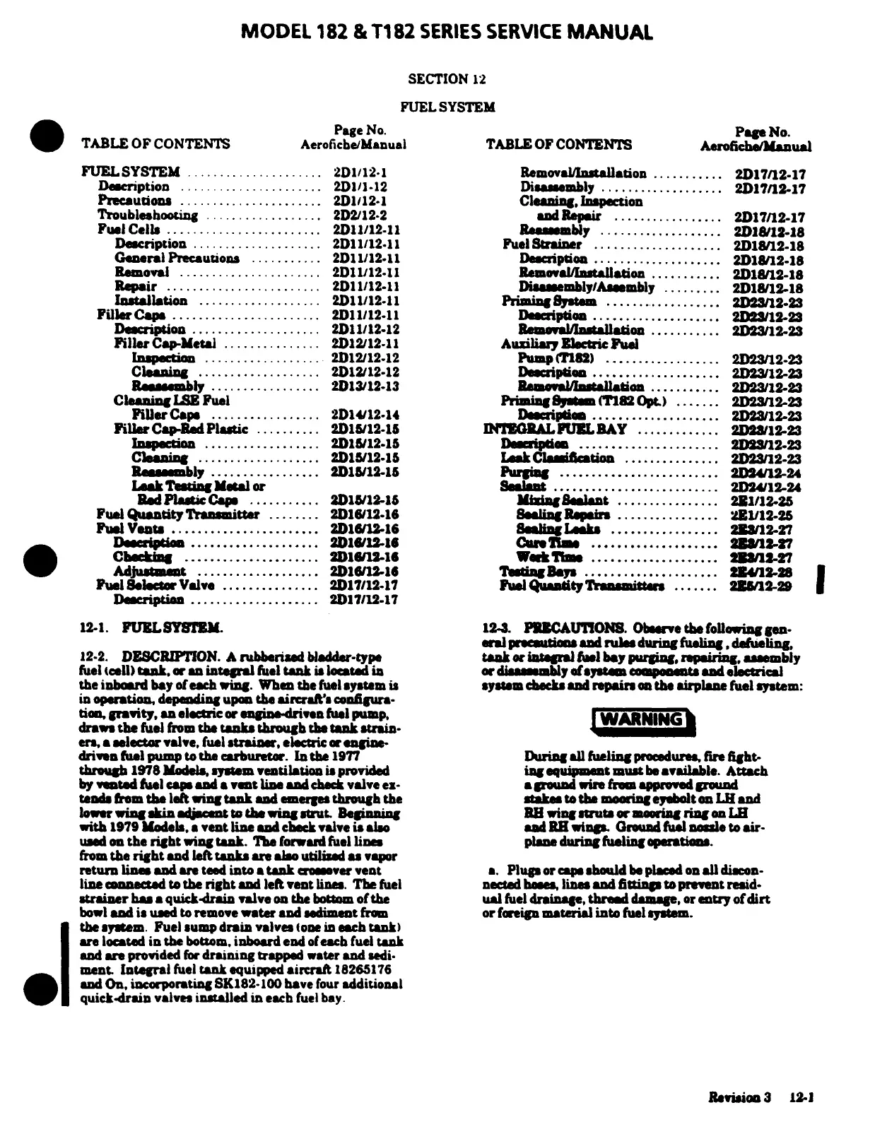
Cessna 182 1978 - Fuel System

Cessna 182 1978
680 pages
Print Icon
To Next Page IconTo Next Page
To Previous Page IconTo Previous Page
Loading...
MODEL
182
&
T182
SERIES
SERVICE
MANUAL
SECTION
12
FUEL
SYSTEM
Page
No.
Page
No.
TABLE
OF
CONTENTS
Aerofiche/Manual
TABLE
OF
CONTENTS
Aerofiche/Manual
FUELSYSTEM
.....................
2D1/12-1
Removal/Installation
...........
2D17/12-17
Description
......................
2D1/1-12
Di
embly
...................
2D17/12-17
Precautions
.....................
2D112-1
Cleaning
Inspection
Troubleshooting
..................
2D2/12-2
and
Repair
..............
2D17/12-17
Fuel
Cells
........................
2D11/1211
Reassembly
.
.............
1812-18
Description
....................
2D11/1211
Fuel
Strainer
....................
2D18/12-18
General
Precautions
...........
2D11/12-11
Description
...................
2D1812-18
Removal
......................
2D11/1211
Removal/Installation
..........
2D1812-18
Repair
........................
2D11/12-11
Dissembly/Assembly
.........
2D18/12-18
Installation
...................
2D11/12-11
Priming System
..................
2D23/12-23
Filler
Caps
.......................
2D11/12.11
Description
....................
2D23/12-23
Description
................
....
................
2D11/12-12
Filler
Cap-Metal
...............
2D12/12.11
Auxiliary
Electric
Fuel
Inspecti
..................
2D12/12-12
Pump(T182)
..................
2D2312-23
Cleaning
...................
2D12/12-12
Reassembly
.................
2D13/12.13
Cleaning
LSE
Fuel
Priming
System
(T182
Opt
.......
2D23/12-23
Filler
Caps
.................
2D14/12-14
Filler
Cap-Red
Plastic
..........
2D15/12-15
Inspection...
..................
2D15/12.15
Description
......................
Cleaning
...................
2D15/12-15
Leak
Classification
...............
2D23/12-23
Leak
Testing
Metal
or
Sealant
.........................
2D24/2-24
Red
Plastic
Caps
...........
2D15/12-15
Fuel
Quantity
Transmitter
........
Fuel
Vents
.......................
2D16/12-16
.................
-
Adjustment
...................
2D16/12-16
Fuel
Selector
Valve
...............
2D17/2.17
Fuel
Quantity
Transmitter
.......
12-1.
FUEL
SYSTEM.
12-3.
al
precautions
and
rules
during
fueling,
defueling,
12-2.
DESCRIPTION.
A
rubberied
bladder-type
tank
or
integral
fuel
bay
purging,
repairing
assembly
fuel
(cell)
tank,
or
and
integral
fuel
tank
is located
in
or
diassembly
of
system
the inboard
bay
of
each
ing.
When
the
fuel
system
is
system
checks
and
repairs
on
the
airplane
fuel system:
in
operation,
depending
upon
the
aircraft'
configura-
tion,
gravity,
an
electric
or engine-driven
fuel
pump,
draws
the
fuel
from
the
tanks
through
the
tank
strain-
er,
a
selector
valve,
fuel
strainer,
electric
or
engine
driven
fuel
pump
to
the
carburetor.
In
the
1977
During
all
fueling procedures
fire
fight-
through
1978
Models,
system
ventilation
is
provided
ing
equipment
must
be
available.
Attach
by
vented
fuel
cap
and
a
vent
line
and
check
valve
ex-
a
round
wire
from
approved
ground
tends
from
the
left
wing
tank
and
emerges
through the
stakes
to
the
mooring
eyebolt
on
L
and
lower
wing
with
1979 Models,
a
vent
line
and
check valve
is
also
and
RH
wings.
Ground
fuel
nozzle
to
air-
used
on
the
right
wing
tank.
The
forward
fuel
lines
plane
during
fueling
operations.
from
the
right
and
left
tanks
are
also
utilied
as
vapor
return
line
and
are
teed
into
a
tank
crossover
vent
a.
Plugs
or
cap
should
be
placed
on
all
discon-
line
connected
to
the
right
and
left
vent
lines.
The
fuel
nected
hoses,
lines
and
fittings
to prevent
reid-
strainer
has
a
quick-drain valve
on
the
bottom
of
the
ual
fuel
drainage,
thread
damage, or
entry
of
dirt
bowl
and
is
used
to remove
water and
sediment
from
or
foreign
material
into
fuel system.
I
the
system.
Fuel sump
drain
valves
(one
in
each
tank)
re
located
in
the
bottom,
inboard
end
of
each
fuel
tank
and are provided
for
draining
trapped
water
and
sedi-
ment.
Integral
fuel
tank
equipped
aircraft
18265176
and
On,
incorporating
SK182-100
have
four
additional
quick-drain
valve
installed in
each
fuel
bay.
Revision
3
12-1

Table of Contents