EasyManua.ls Logo

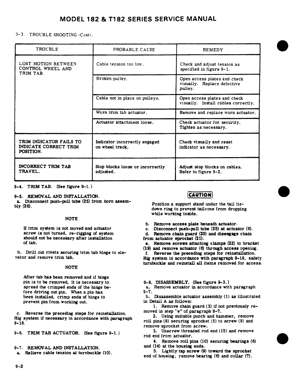
Cessna 182 1978 - Trim Tab; Trim Tab Actuator

Cessna 182 1978
680 pages
Print Icon
To Next Page IconTo Next Page
To Previous Page IconTo Previous Page
Loading...
MODEL
182
&
T182
SERIES
SERVICE
MANUAL
9-3.
TROUBLE
SHOOTING
(Cont).
TROUBLE
PROBABLE
CAUSE
REMEDY
LOST
MOTION
BETWEEN
Cable
tension
too
low.
Check
and
adjust
tension
as
CONTROL
WHEEL
AND
specified
in
figure
9-1.
TRIM
TAB.
Broken
pulley.
Open
access
plates
and
check
visually.
Replace
defective
pulley.
Cable
not
in
place
on
pulleys.
Open
access
plates
and
check
visually.
Install
cables
correctly.
Worn
trim
tab
actuator.
Remove
and
replace
worn
actuator.
Actuator
attachment
loose.
Check
actuator
for
security.
Tighten
as
necessary.
TRIM
INDICATOR
FAILS
TO
Indicator
incorrectly
engaged
Check
visually
and
reset
INDICATE
CORRECT
TRIM
on
wheel
track.
indicator
as
necessary.
POSITION.
INCORRECT
TRIM
TAB
Stop
blocks
loose
or
incorrectly
Adjust
stop
blocks
on
cables.
TRAVEL.
adjusted.
Refer
to
figure
9-2.
9-4.
TRIM
TAB.
(See
figure
9-1.)
9-5.
REMOVAL
AND
INSTALLATION.
a.
Disconnect
push-pull
tube
(25)
from
horn
assem-
bly
(26).
Position
a
support stand
under
the
tail
tie-
down
ring
to
prevent
tailcone
from
dropping
while
working
inside.
NOTE
b.
Remove
access
plate
beneath
actuator.
If
trim
system
is
not
moved
and
actuator
c.
Disconnect
push-pull
tube
(25)
at
actuator
(6).
screw
is
not
turned,
re-rigging
of
system
d.
Remove
chain
guard
(20)
and
disengage
chain
should
not
be
necessary
after
installation
from
actuator
sprocket
(21).
of
tab.
e.
Remove
screws
attaching
clamps
(22)
to
bracket
(19)
and
remove
actuator
(6)
through
access
opening.
b.
Drill
out
rivets
securing
trim
tab
hinge
to
ele-
f.
Reverse
the
preceding
steps
for
reinstallation.
vator
and
remove
trim
tab.
Rig
system
in
accordance
with
paragraph
9-18,
safety
turnbuckle
and
reinstall
all
items
removed
for
access.
NOTE
After
tab
has
been
removed
and
if
hinge
pin
is
to
be
removed,
it
is
necessary
to
9-8.
DISASSEMBLY.
(See
figure
9-3.)
spread
the
crimped
ends
of
the hinge
be-
a.
Remove
actuator
in
accordance
with
paragraph
fore
driving
out
pin.
When
a
pin
has
9-7.
been
installed.
crimp
ends
of
hinge
to
b.
Disassemble
actuator
assembly
(1)
as
illustrated
prevent
pin
from
working
out.
in
Detail
A
as
follows:
1.
Remove
chain
guard
(3)
if
not
previously
re-
c.
Reverse
the
preceding
steps
for
reinstallation.
moved
in
step
"e"
of
paragraph
9-7.
Rig
system
if
necessary
in
accordance
with
paragraph
2.
Using
sutable
punch
and
hammer,
remove
remove
sprocket
from
screw.
9-6.
TRIM
TAB
ACTUATOR.
(See
figure
9-1.)
3.
Unscrew
threaded
rod
end
(15)
and
remove
rod
end
from
actuator.
4.
Remove
roll
pins
(10)
securing
bearings
(6)
9-7.
REMOVAL
AND
INSTALLATION.
and
(14)
at
the
housing
ends.
a.
Relieve
cable
tension
at
turnbuckle
(10).
5.
Lightly
tap
screw
(9)
toward
the
sprocket
end
of
housing,
remove
bearing
(6)
and
collar
(7).
9-2

Table of Contents