EasyManua.ls Logo

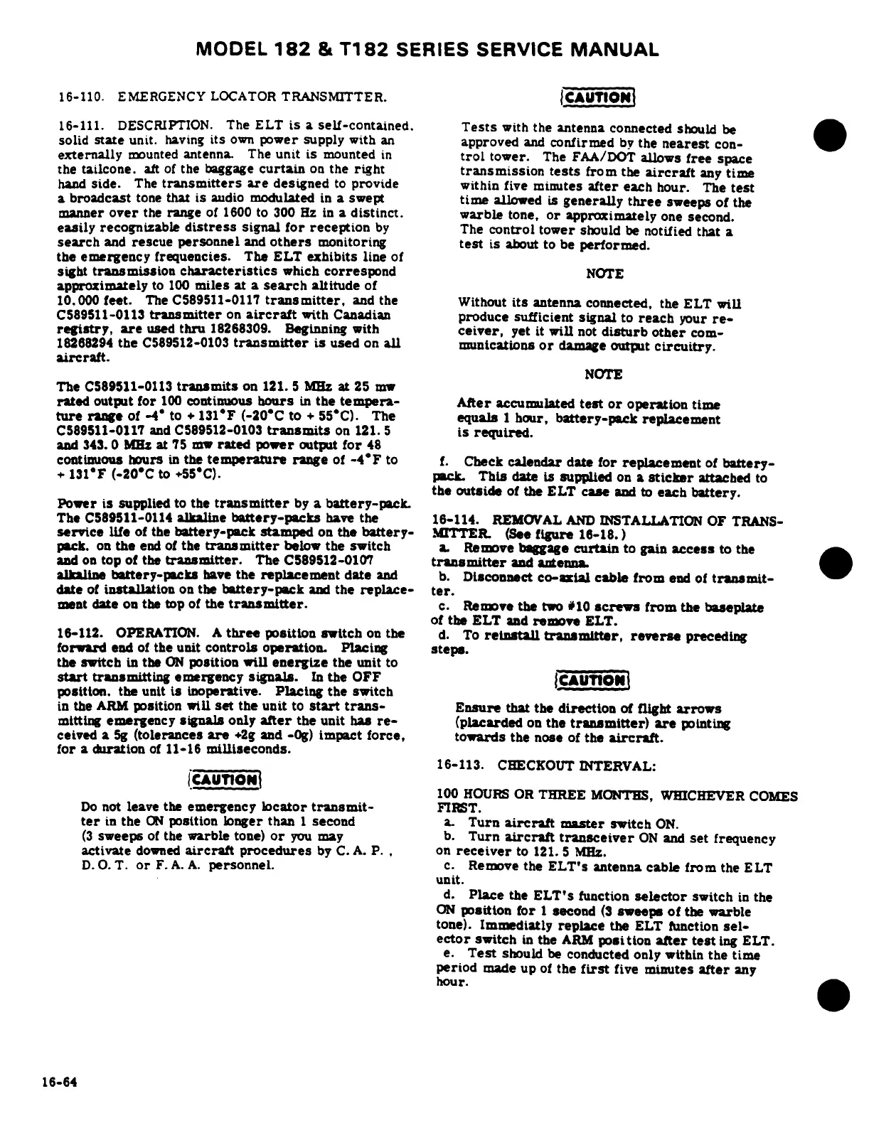
Cessna 182 1978 - Checkout Interval; Description; Emergency Locator Transmitter (Beginning with 18265361); Operation

Cessna 182 1978
680 pages
Print Icon
To Next Page IconTo Next Page
To Previous Page IconTo Previous Page
Loading...
MODEL
182
&
T182
SERIES
SERVICE
MANUAL
16-110.
EMERGENCY
LOCATOR
TRANSMITTER.
CAUTION
16-111.
DESCRIPTION.
The
ELT
is
a
self-contained.
Tests
with
the
antenna
connected
should
be
solid
state
unit.
having
its
own
power
supply
with
an
approved
and
confirmed
by
the
nearest
con-
externally
mounted
antenna.
The
unit
is
mounted
in
trol
tower.
The
FAA/DOT
allows
free
space
the
tailcone.
aft
of
the
baggage
curtain
on
the
right
transmission
tests
from
the
aircraft
any
time
hand
side.
The
transmitters
are
designed
to
provide
within
five
minutes
after
each
hour.
The
test
a
broadcast
tone
that
is
audio
modulated
in
a
swept
time
allowed
is
generally
three
sweeps
of
the
manner
over
the
range
of
1600
to
300
Hz
in
a
distinct.
warble
tone,
or
approximately
one
second.
easily
recognizable
distress
signal
for
reception
by
The
control
tower
should
be
notified
that
a
search
and
rescue
personnel
and
others
monitoring
test
is
about
to
be
performed.
the
emergency
frequencies.
The
ELT
exhibits
line
of
sight
transmission
characteristics
which
correspond
NOTE
approximately
to
100
miles
at
a
search
altitude
of
10.000
feet.
The
C589511-0117
transmitter,
and
the
Without
its
antenna
connected,
the
ELT
will
C589511-0113
transmitter
on
aircraft
with
Canadian
produce
sufficient
signal
to
reach
your
re-
registry,
are
used
thru
18268309.
Beginning
with
ceiver,
yet
it
will
not
disturb
other
com-
18268294
the
C589512-0103
transmitter
is
used
on
all
munications
or
damage
output
circuitry.
aircraft.
NOTE
The
C589511-0113
transmits
on
121.
5
MHz
at
25
mw
rated
output
for
100
continuous
hours
in
the
tempera-
After
accumulated
test
or
operation
time
ture
range
of -4°
to
+
131°F
(-20-C
to
+
55-C).
The
equals
1
hour,
battery-pack
replacement
C589511-0117
and
C589512-0103
transmits
on
121.
5
is
required.
and
343.
0
MHz
at
75
mw
rated
power
output
for
48
continuous
hours
in
the
temperature
range
of
-4°F
to
f.
Check
calendar
date
for
replacement
of
battery-
+
131°F
(-20°C
to
+55°C).
pack.
This
date
is
supplied
on
a
sticker
attached
to
the
outside
of
the ELT
case
and to
each
battery.
Power
is
supplied
to
the
transmitter
by
a
battery-pack.
The
C589511-0114
alkaline
battery-packs
have
the
16-114.
REMOVAL
AND
INSTALLATION
OF
TRANS-
service
life
of
the
battery-pack
stamped
on
the
battery-
MITTER
(See
figure
16-18.)
pack.
on
the
end
of
the
transmitter
below
the switch
a.
Remove
baggage
curtain
to
gain
access
to
the
and
on
top
of
the
transmitter.
The
C589512-0107
transmitter
and
antenna.
alkaline
bttery-packs
have
the
replacement
date
and
b.
Disconnect
co-axial
cable
from
end
of
transmit-
date
of
installation
on
the
battery-pack
and
the
replace-
ter.
ment
date
on
the
top
of
the
transmitter.
c.
Remove
the
two
#10
screws
from
the
baseplate
of
the
ELT
and
remove
ELT.
16-112.
OPERATION.
A
three
position
switch
on
the
d.
To
reinstall
transmitter,
reverse
preceding
forward
end
of
the
unit
controls
operation.
Placing
steps.
the
switch
in
the
ON
position
will
energize
the
unit
to
start
transmitting
emergency
signals.
In
the
OFF
position.
the
unit
is
inoperative.
Placing
the
switch
in
the
ARM
position
will
set
the
unit
to
start
trans-
Ensure
that
the
direction
of
flight
arrows
mitting
emergency
signals
only
after
the
unit
has
re-
(placarded
on
the
transmitter)
are
pointing
ceived
a
5g
(tolerances
are
+2g
and
-0g)
impact
force,
towards
the
nose
of
the
aircraft.
for
a
duration
of
11-16
milliseconds.
16-113.
CHECKOUT
INTERVAL:
- ----
- -
100
HOURS
OR
THREE
MONTHS,
WHICHEVER
COMES
Do
not
leave
the
emergency
locator
transmit-
FIRST.
ter
in
the
ON
position
longer
than
1
second
a.
Turn
aircraft
master
switch
ON.
(3
sweeps
of
the
warble
tone)
or
you
may
b.
Turn
aircraft
transceiver
ON
and
set
frequency
activate
downed
aircraft
procedures
by
C.
A.
P.
,
on
receiver
to
121.
5
MHz.
D.
O.
T.
or
F.
A.
A.
personnel.
c.
Remove
the
ELT's
antenna
cable
from
the
ELT
unit.
d.
Place
the
ELT's
function
selector
switch
in
the
ON
position
for
1
second
(3
sweeps
of
the
warble
tone).
Immediatly
replace
the
ELT
function
sel-
ector
switch
in
the
ARM
position
after
test
ing
ELT.
e.
Test
should
be
conducted
only
within
the
time
period
made
up
of
the
first
five
minutes
after
any
hour.
16-64

Table of Contents