EasyManua.ls Logo

Cessna 182 1978 - Electric Clock; Outside Air Temperature Gage

Cessna 182 1978
680 pages
Print Icon
To Next Page IconTo Next Page
To Previous Page IconTo Previous Page
Loading...
MODEL
182
&
T182
SERIES
SERVICE
MANUAL
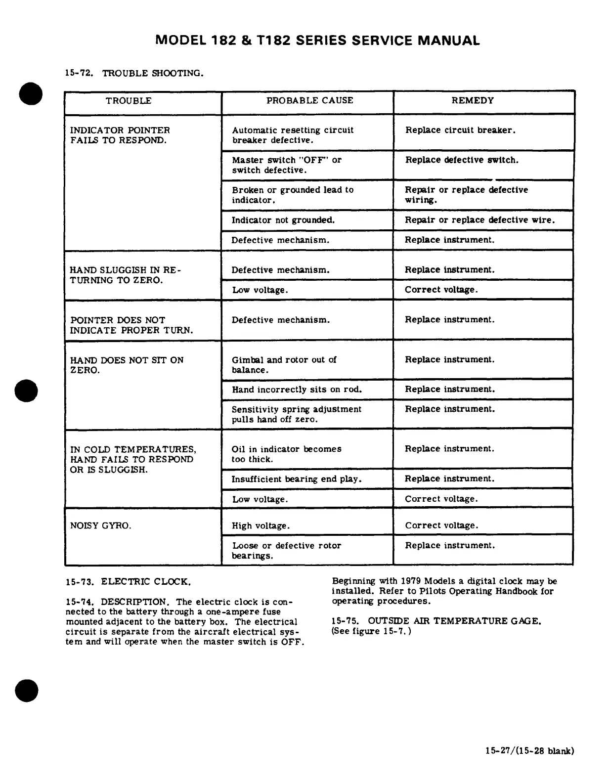
15-72.
TROUBLE
SHOOTING.
TROUBLE
PROBABLE
CAUSE
REMEDY
INDICATOR
POINTER
Automatic
resetting
circuit
Replace
circuit
breaker.
FAILS
TO
RESPOND.
breaker
defective.
Master
switch
"OFF"
or
Replace
defective switch.
switch
defective.
Broken
or
grounded
lead
to
Repair
or
replace
defective
indicator.
wiring.
Indicator
not
grounded.
Repair
or
replace
defective
wire.
Defective
mechanism.
Replace
instrument.
HAND
SLUGGISH
IN
RE-
Defective
mechanism.
Replace
instrument.
TURNING
TO
ZERO.
Low
voltage.
Correct
voltage.
POINTER
DOES
NOT
Defective
mechanism.
Replace
instrument.
INDICATE
PROPER
TURN.
HAND
DOES
NOT
SIT
ON
Gimbal
and
rotor
out
of
Replace
instrument.
ZERO.
balance.
Hand
incorrectly
sits
on
rod.
Replace
instrument.
Sensitivity
spring
adjustment
Replace
instrument.
pulls
hand
off
zero.
IN
COLD
TEMPERATURES,
Oil
in
indicator
becomes
Replace
instrument.
HAND
FAILS
TO
RESPOND
too
thick.
OR
IS
SLUGGISH.
Insufficient
bearing
end
play.
Replace
instrument.
Low
voltage.
Correct
voltage.
NOISY GYRO.
High
voltage.
Correct
voltage.
Loose
or
defective
rotor
Replace
instrument.
bearings.
15-73.
ELECTRIC
CLOCK.
Beginning
with
1979
Models a
digital
clock
may
be
installed.
Refer
to
Pilots
Operating
Handbook
for
15-74.
DESCRIPTION.
The
electric
clock
is
con-
operating
procedures.
nected
to
the
battery
through
a
one-ampere
fuse
mounted
adjacent
to
the
battery
box.
The
electrical
15-75.
OUTSIDE
AIR
TEMPERATURE
GAGE.
circuit
is
separate
from
the
aircraft
electrical
sys-
(See
figure
15-7.)
tern
and
will
operate
when
the
master
switch
is
OFF.
15-27/(15-28
blank)

Table of Contents