EasyManua.ls Logo

Cessna 182 1978 - Torque Links; Removal of Torque Links; Installation of Torque Links; Shimmy Damper

Cessna 182 1978
680 pages
Print Icon
To Next Page IconTo Next Page
To Previous Page IconTo Previous Page
Loading...
MODEL
182
&
T182
SERIES
SERVICE
MANUAL
2
\
\
\
Tighten
bolts
(8)
to
20-25
pound-
4
3
4'
\ \ \
\
Y\t
l
(0inches,
then
safety
bolts
by
ben-
1
2
\\
-^
\yci
®
10
ding
tips
of
safety
lug
(10).
Tighten
nuts
(7)
snugly,
then
(M
,-8
tighten
to
align
next
castellation
· J^y~// </~7 ^!with
cotter
pin
hole.
//
y^-.Y
^ 7
~P/N
S1450-6B14-010
washers
(3)
7 /^
-"
J¢L-
*\
I'
sare
available
to
use
as
required
to
remove
any
looseness.
~\4
.\
\
Apply
MIL-G-81322A
General
Purpose
Grease
to
all
grease
fittings
(2).
3
1.
Spacer
6.
Upper
Torque
Link
>
X\ \
9
2.
Grease
Fitting
7.
Nut
r
\ \
4
3.
Washer
8.
Bolt
}
\
\
3
4.
Bushing
9.
Lower
Torque
Link
r
\ •2
5.
Stop
Lug
10.
Safety
Lug
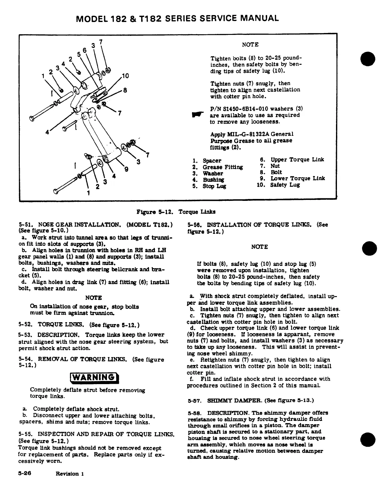
Figure
5-12.
Torque
Links
5-51.
NOSE
GEAR
INSTALLATION.
(MODEL
T182.)
5-56.
INSTALLATION
OF
TORQUE
LINKS.
(See
(See
figure
5-10.)
figure
5-12.)
a.
Work
strut
into
tunnel
area
so
that
legs
of
trunni-
on
fit
into
slots
of
supports
(3).
b.
Align
holes
in
trunnion
with
holes
in
RH
and
L
NOTE
gear
panel
walls
(1)
and
(8)
and
supports
(3);
install
bolts,
bushings,
washers
and
nuts.
If
bolts
(8),
safety
lug
(10)
and
stop
lug
(5)
c.
Install
bolt
through
steering
bellcrank
and
bra-
were
removed
upon
installation,
tighten
cket
(5).
bolts
(8)
to
20-25
pound-inches,
then
safety
d.
Align
holes
in
drag
link
(7)
and
fitting
(6);
install
the
bolts
by
bending
tips
of
safety
lug
(10).
bolt,
washer
and
nut.
NOTE
a.
With
shock
strut
completely
deflated,
install
up-
On
installation
of
nose
gear,
stop
bolts
per
and
lower
torque
link
assemblies.
b.
Install
bolt
attaching
upper
and
lower
assemblies.
c.
Tighten
nuts
(7)
snugly,
then
tighten
to
align
next
5-52.
TORQUE
LINKS.
(See
figure
5-12.)
castellation
with
cotter
pin
hole
in
bolt.
d.
Check
upper
torque
link
(6)
and
lower
torque
link
5-53.
DESCRIPTION.
Torque
links
keep
the
lower
(9)
for
looseness.
If
looseness
is
apparant,
remove
strut
aligned
with
the
nose
gear
steering
system,
but
nuts
(7)
and
bolts,
and
install
washers
(3)
as necessary
permit
shock
strut
action.
to
take
up
any
looseness.
This
will
assist
in
prevent-
ing
nose
wheel
shimmy.
5-54.
REMOVAL
OF
TORQUE
LINKS.
(See
figure
e.
Retighten
nuts
(7)
snugly,
then
tighten
to
align
5-12.)
next
castellation
with
cotter
pin
hole
in
bolt;
install
[WARNING'
cotter
pin.
f.
Fill
and
inflate
shock
strut
in
accordance
with
Com
y d
e s t
b
e
r
ving
procedures
outlined
in
Section
2
of
this
manual
Completely
deflate
strut
before
removing
torque
links.
5-57.
SHIMMY
DAMPER.
(See
figure
5-13.)
a.
Completely
deflate
shock
strut.
b.
Disconnect
upper
and
lower
attaching
bolts,
5-58.
DESCRITION.
The
shimmy
damper
offers
spacers,
shims
and
nuts;
remove
torque
links.
resistance
to
shimmy
by
forcing
hydraulic
fluid
through
small
orifices
in
a
piston.
The
damper
5-55.
INSPECTION
AND
REPAIR
OF
TORQUE
LINKS.
piston
shaft
is
secured
to
a
stationary
part,
and
(See
figure
5-12.)
housing
is
secured
to
nose
wheel
steering
torque
arm
assembly,
which
moves
as
nose
wheel
is
Torque
link
bushings
should
not
be
removed
except
am
a
sembly,
which
moe
as
nos
wheel
is
for
replacement
of
parts.
Replace
parts
only
if
ex-
turned,
causing
relativ
motion
between
damper
cessively
worn.
shaft
and
housing.
cessivey
worn.evision
1
5-26
Revision
1

Table of Contents