EasyManua.ls Logo

Cessna 182 1978 - Copilots Control Column; Aileron Bellcrank; Aileron Installation

Cessna 182 1978
680 pages
Print Icon
To Next Page IconTo Next Page
To Previous Page IconTo Previous Page
Loading...
MODEL
182
&
T182
SERIES
SERVICE
MANUAL
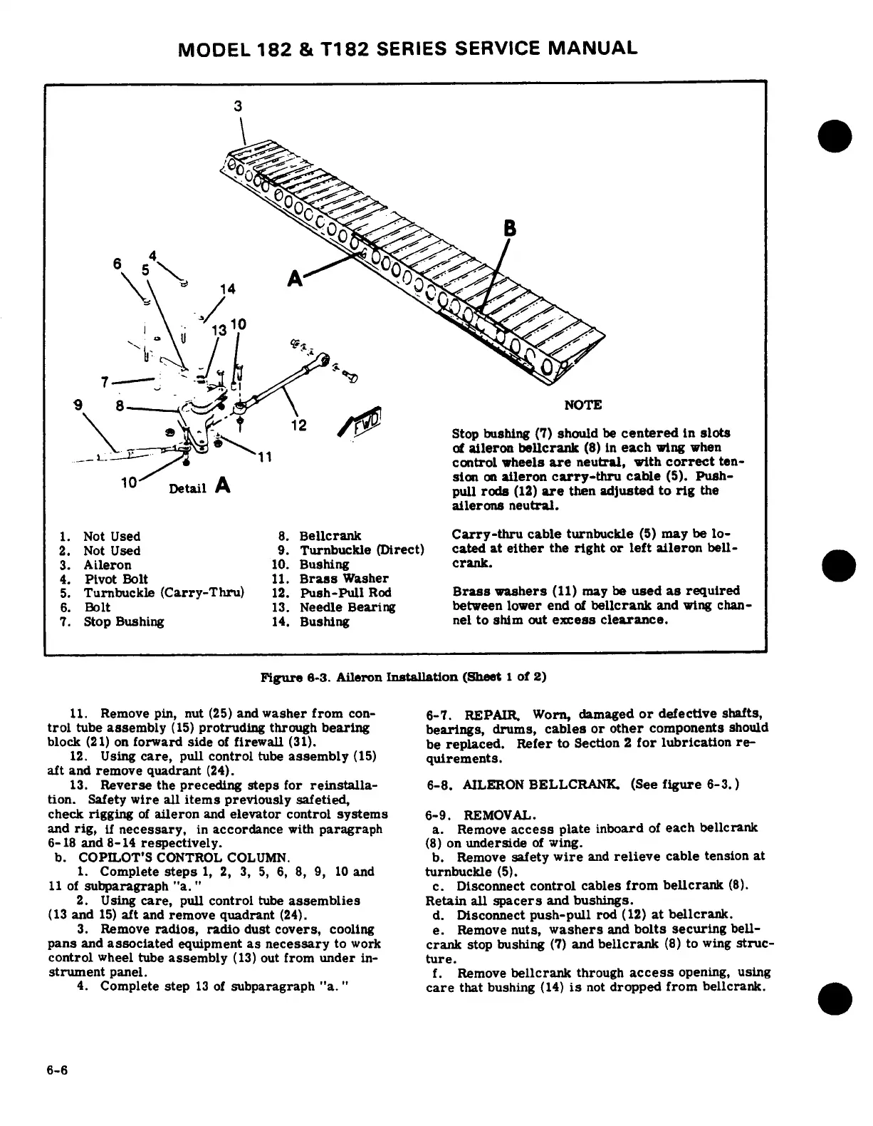
3
9
a ~\ °® H ~ ^~1-~^
Stop
bushing
(7)
should
be
centered
in
slots
11
>-i
e
@
.
of
aileron
bellcrank
(8)
in
each
wing
when
... ~L-- ,
1
"
control
wheels
are
neutral,
with
correct
ten-
10
.. ^
a
A
sion
on
aileron
carry-thru
cable
(5).
Push-
1v
Detail
A
pull
rods
(12)
are
then
adjusted
to
rig
the
ailerons neutral.
1.
Not
Used
8.
Bellcrank
Carry-thru
cable turnbuckle
(5)
may
be
lo-
2.
Not
Used
9.
Turnbuckle
(Direct)
cated
at either
the
right
or
left
aileron
bell-
3.
Aileron
10.
Bushing
crank.
4.
Pivot
Bolt
11.
Brass
Washer
5.
Turnbuckle
(Carry-Thru)
12.
Push-Pull
Rod
Brass
washers
(11)
may
be
used
as
required
6.
Bolt
13.
Needle
Bearing
between
lower
end
of
bellcrank
and
wing chan-
7.
Stop
Bushing
14.
Bushing
nel
to
shim
out
excess clearance.
Figure
6-3.
Aileron
Installation
(Sheet
1
of
2)
11.
Remove
pin, nut
(25)
and
washer from
con-
6-7.
REPAIR.
Worn,
damaged
or
defective
shafts,
trol
tube
assembly
(15)
protruding
through
bearing
bearings,
drums,
cables
or
other
components
should
block
(21) on
forward
side
of
firewall
(31).
be
replaced.
Refer
to
Section
2
for
lubrication
re-
12.
Using
care,
pull
control
tube
assembly
(15)
quirements.
aft
and
remove quadrant
(24).
13.
Reverse
the
preceding steps
for
reinstalla-
6-8.
AILERON
BELLCRANK.
(See
figure
6-3.)
tion.
Safety
wire
all
items
previously
safetied,
check
rigging
of
aileron
and
elevator
control
systems
6-9.
REMOVAL.
and
rig,
if
necessary,
in
accordance
with
paragraph
a. Remove
access
plate
inboard
of
each
bellcrank
6-18
and
8-14
respectively.
(8)
on
underside
of
wing.
b.
COPILOT'S
CONTROL
COLUMN.
b.
Remove
safety
wire
and
relieve
cable
tension
at
1.
Complete
steps
1,
2,
3, 5,
6,
8, 9,
10
and
turnbuckle
(5).
11
of
subparagraph
"a.
"
c.
Disconnect
control
cables
from bellcrank
(8).
2.
Using
care,
pull
control
tube
assemblies
Retain
all
spacers
and
bushings.
(13
and
15)
aft
and
remove
quadrant
(24).
d.
Disconnect
push-pull
rod
(12)
at bellcrank.
3.
Remove
radios,
radio
dust
covers,
cooling
e.
Remove
nuts,
washers
and
bolts
securing
bell-
pans
and
associated
equipment
as
necessary
to
work
crank
stop
bushing
(7)
and
bellcrank
(8)
to
wing
struc-
control
wheel
tube
assembly
(13)
out
from
under
in-
ture.
strument
panel.
f.
Remove
bellcrank
through
access
opening,
using
4.
Complete
step
13
of
subparagraph
"a.
"
care
that
bushing
(14)
is
not
dropped
from
bellcrank.
6-6

Table of Contents