EasyManuals Logo

Chroma A620028 User Manual

Default Icon
238 pages
To Next Page IconTo Next Page
To Previous Page IconTo Previous Page
Page #172 background imageLoading...
Page #172 background image
Programmable DC Power Supply (with Solar Array Simulation) 62000H Series
Operating & Programming Manual
5-2
Table 5-1
Pin No.
INPUT/OUTPUT
Description
1
---
“N.C.”
2
INPUT
RxD
3
OUTPUT
TxD
4
---
DSR
5
---
GND
6
---
DTR
7
---
CTS
8
---
RTS
9
---
“N.C.”
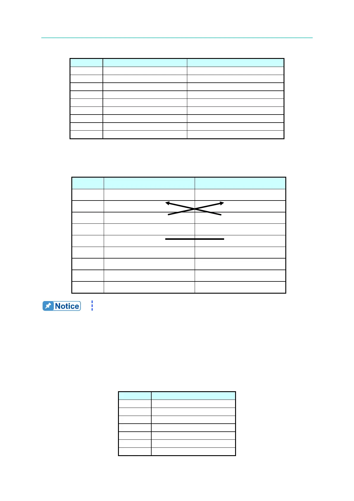
Table 5-2 lists the connections between the PC (IBM compatible) and the 62000H Series DC
Power Supply.
Table 5-2
Pin No.
IBM PC
62000H
1
DCD
“N.C.
2
RX
RX
3
TX
TX
4
DTR
“N.C.
5
GND
DGND
6
DSR
“N.C.
7
RTS
“N.C.
8
CTS
“N.C.
9
“N.C.
“N.C.
“N.C.” stands for “Not Connected”.
5.1.4 Connecting RS-485
The default baudrate of the 62000H Series DC Power Supply is set to 115200 and the parity
check is set to None. The RS-485 interface is a half-duplex two-wire differential signaling
transmission system and only RS485_P and RS485_N signals are required for data
transmission. The connector is the same as the RS-232C (9-pin D type male). Table 5-3 lists
the pins and signals of the RS-485 connector.
Table 5-3
Pin No.
Description
1
---
2
---
3
---
4
RS485_P
5
---
6
---
7
---

Table of Contents

Questions and Answers:

Question and Answer IconNeed help?

Do you have a question about the Chroma A620028 and is the answer not in the manual?

Chroma A620028 Specifications

General IconGeneral
BrandChroma
ModelA620028
CategoryPower Supply
LanguageEnglish

Related product manuals