Manual Operation
Figure 3-10
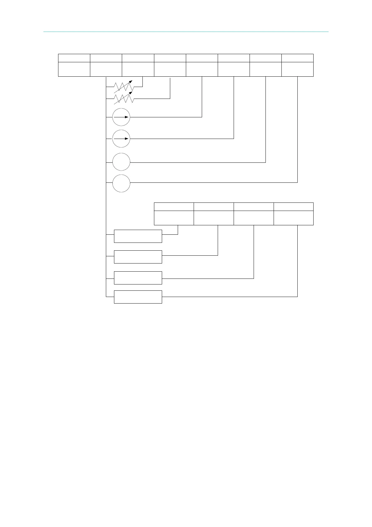
APG Interface pin definitions:
1. Auxiliary power Vcc: outputs +12Vdc with a maximum output current of 10mA (output
port).
2. Voltage programming: inputs the resistance (0-5K Ohm) between this pin and APIGND to
linearly control the output voltage (CV mode).
3. Voltage programming: inputs the analog current (4-20mA) between this pin and APIGND
to linearly control the output voltage (CV mode).
4. Voltage programming: inputs the analog voltage (0-5Vdc or 0-10Vdc) between this pin
and APIGND to linearly control the output voltage (CV mode).
5. Voltage measurement: outputs the analog current (4mA-20mA) for monitoring.
6. Voltage measurement: outputs the analog voltage (0-5V or 0-10V) for monitoring.
14. APIGND: This contact is the reference potential of the APG interface. The potential is
isolated between the APG and chassis with a maximum voltage differential of 70Vdc.
15. Current programming: inputs the resistance (0-5K Ohm) between this pin and APIGND to
linearly control the output current (CC mode).
16. Current programming: inputs the analog current (4-20mA) between this pin and APIGND
to linearly control the output current (CC mode).
5 18 6 19
1
+12VAPI API GND AVO_SET_R AIO_SET_R AVO_SET_C AIO_SET_C AVO_SET_V AIO_SET_V
AVO_MEAS_C AIO_MEAS_C AVO_MEAS_V AIO_MEAS_V
14 2 15 3
16 4
17
- +
- +
sensing
sensing
sensing
sensing