Programmable DC Power Supply (with Solar Array Simulation) 62000H Series
Operating & Programming Manual
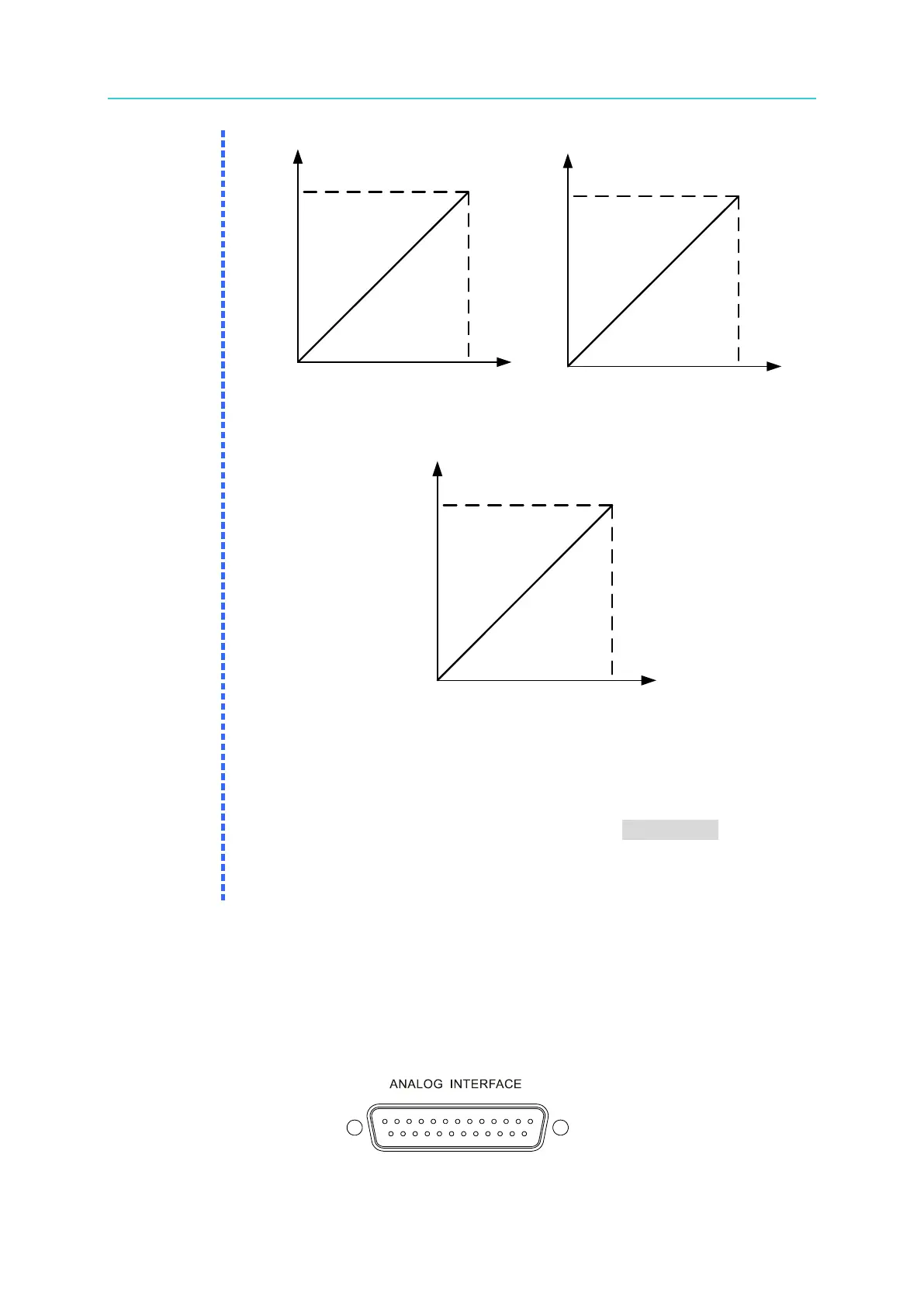
DC SOURCE MEAS
600V/25A
APG OUTPUT 5V
DC SOURCE MEAS
APG OUTPUT 10V
600V/25A
(a) (b)
DC SOURCE MEAS
APG OUTPUT 4
mA~20mA
600V/25A
(c)
Figure 3-8
3. Calibrate the APG settings and measurements before using APG
control.
4. When setting the APG VMEAS/APG IMEAS to Iref(4-20mA) mode,
ensure the series resistance does not exceed 500Ω so the DC Power
Supply outputs the correct values. Ensure the resistor wattage is
sufficient to avoid damaging the resistor.
3.3.1.1.1 Pin Assignment of the APG Control Interface
The APG interface is a bi-directional interface utilizing analog signals. The connector is
located on the rear panel and its pin assignments are shown in Figure 3-9, Figure 3-10, and
Appendix A.
Figure 3-9