Manual Operation
Figure 3-28
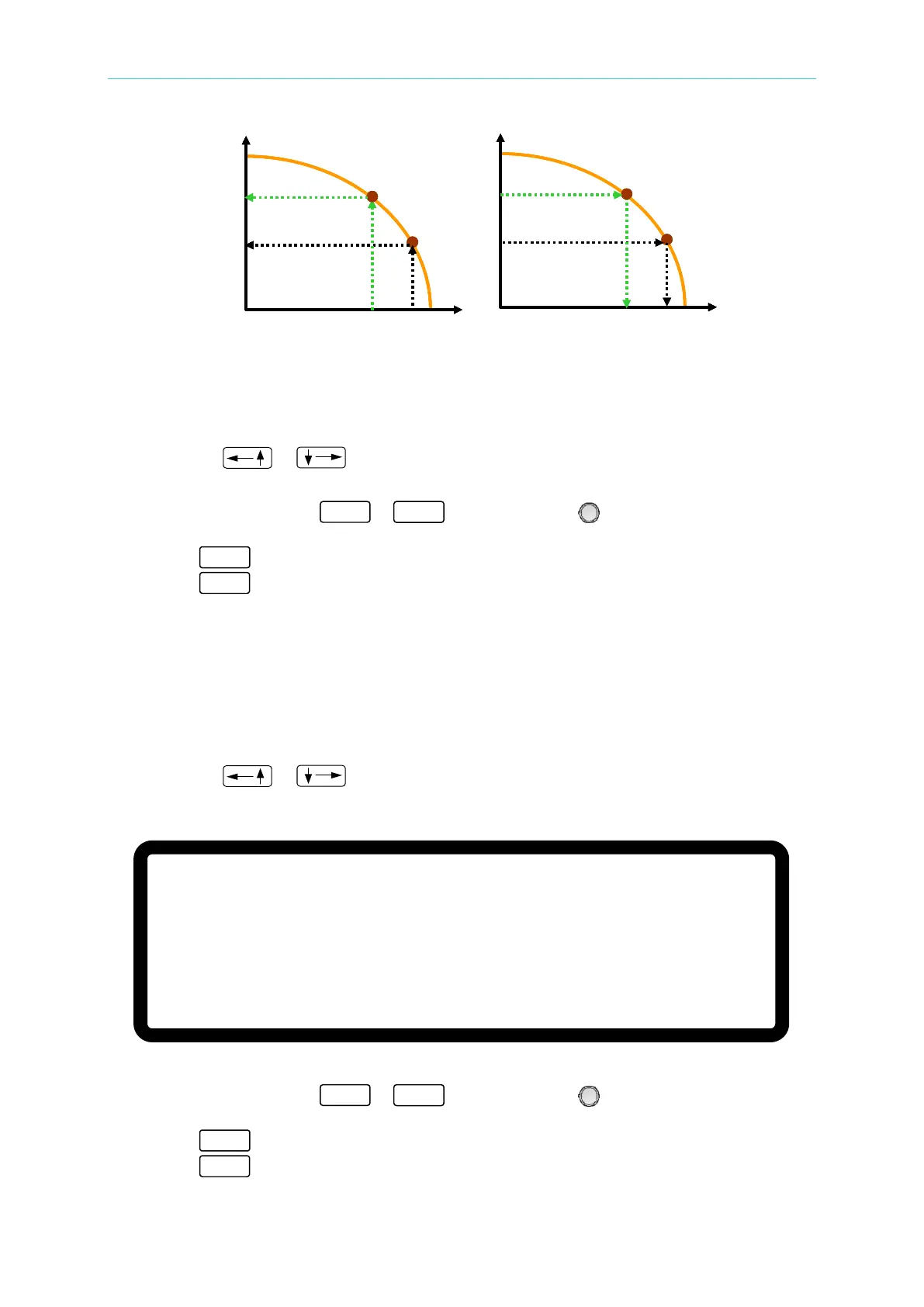
Set the CONTROL MODE as described below:
1. Use the “
”, “ ” keys to move the cursor to the column to be set as shown in
Figure 3-27.
2. Use the numeric keys (
- ) or the “Rotary” ( ) knob to select either CC
MODE or CV MODE. The default setting is CC MODE.
3. Press “ ” to confirm.
4. Press “
” to return to the MAIN PAGE.
3.3.2.6.2 Setting INPUT FILTER
INPUT FILTER filters the measured signals for the IV Curve calculation used in IV mode. For
example, if the measured voltage waveform has 20 kHz ripple then setting the INPUT FILTER
to 1kHz can eliminate the 20 kHz ripple component.
1. Use the “
”, “ ” keys to move the cursor to the column to be set as shown in
Figure 3-29.
Figure 3-29
2. Use the numeric keys (
- ) or the “Rotary” ( ) knob to set the INPUT
FILTER frequency. The setting range is 1-3125Hz and the default is 1000Hz.
3. Press “ ” to confirm.
4. Press “
” to return to the MAIN PAGE.
Voc
Isc
V1
Iset1
V2
Iset2
(a) CC Mode
Voc
Isc
Vset1
I1
Vset2
I2
(b) CV Mode
Voc
Isc
V1
Iset1
V2
Iset2
Voc
Isc
V1
Iset1
V2
Iset2
(a) CC Mode
Voc
Isc
Vset1
I1
Vset2
I2
(b) CV Mode
[O U T P U T S E T U P]
I V C U R V E P A R A M E T E R:
C O N T R O L M O D E = C C M O D E
I N P U T F I L T E R = 1 0 0 0 Hz
_
O U T P U T S P E E D = M I D D L E
S E T T I N G M A R G I N = 3 %
▲