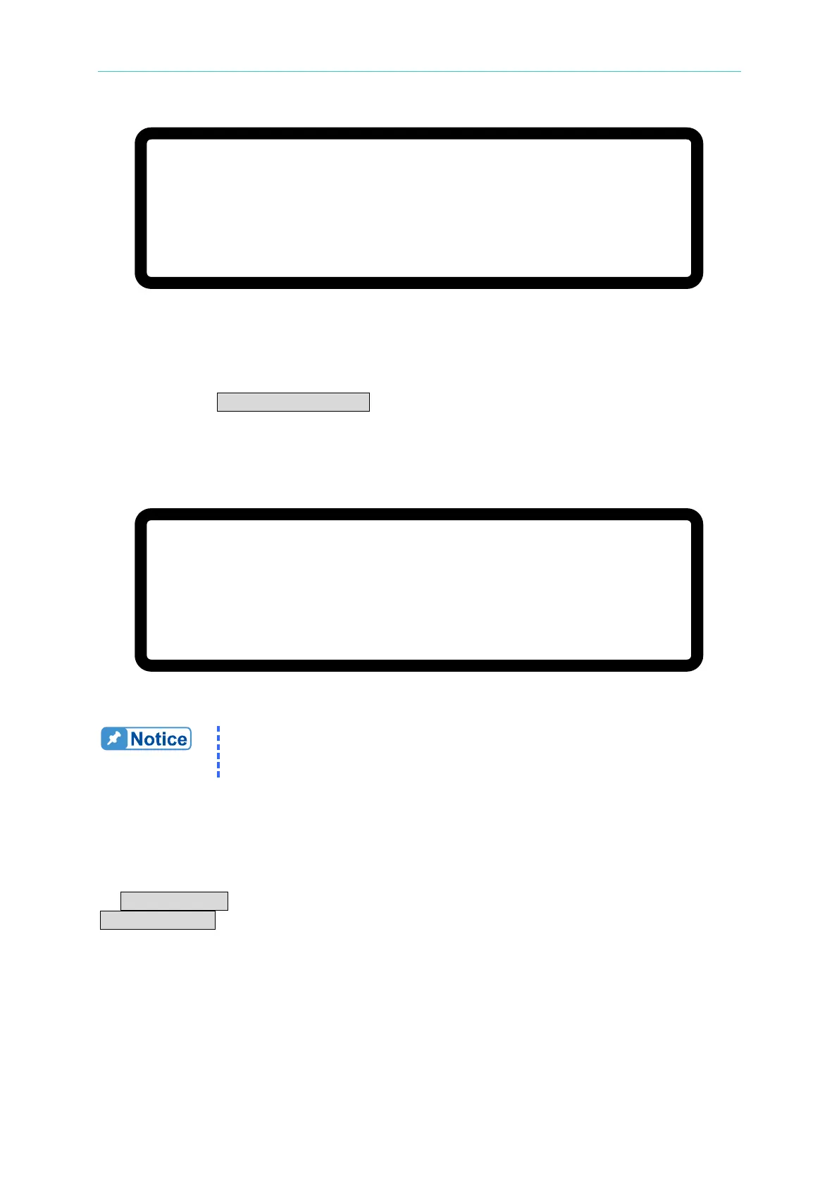
Manual Operation
V
=
6 0.
0 0 _
V
∑ I
= 1 0. 0 0
A M S T O F F
0
. 0 0 0 0
V
0 .
0 0 0 0
A
0 .
0
W
Figure 3-52
3.3.3.5.2 Setting SYSTEM SETUP for Parallel
The operation of POWER ON STATUS in [SYSTEM SETUP] for parallel operation is the
same as for a single unit except the output current will increase based on the number of units
connected in parallel. For example, if there are 5 sets of 62150H-600S in parallel, the
maximum output voltage that can be set is 600V, and the maximum output current is 125A, as
shown in
Figure 3-53 below:
[S Y S T E M S E T U P
]
A P G V S E T
=
N O N E
A P G I S E T
=
N O N E
A P G V M E A S
= N O N E
A P G I M E A S
=
N O N E
B U Z Z E R
= O N
P O W E R O N S T A T E S
=
U S E R D E F I N I T I O N
_
∑ V
=
6 0 0
.
0 0 V I
= 1 2 5
. 0 0
A O U T P U T = O F F
Figure 3-53
It will return to single unit mode once the POWER ON STATUS is set in
parallel mode. The POWER ON STATUS sets the output voltage and
current to 0 and OUTPUT to OFF automatically.
3.3.3.5.3 Setting OUTPUT SETUP for Parallel
The I LIMIT MAX in [OUTPUT SETUP] in the MASTER unit in a parallel connection will
increase based on the number of units connected in parallel. The current setting is indicated
by ΣV LIMIT: MAX for easy identification as shown in Figure 3-54 below. The setting range of
ΣV SLEW RATE will also increase based on the number of units connected in parallel.