Manual Operation
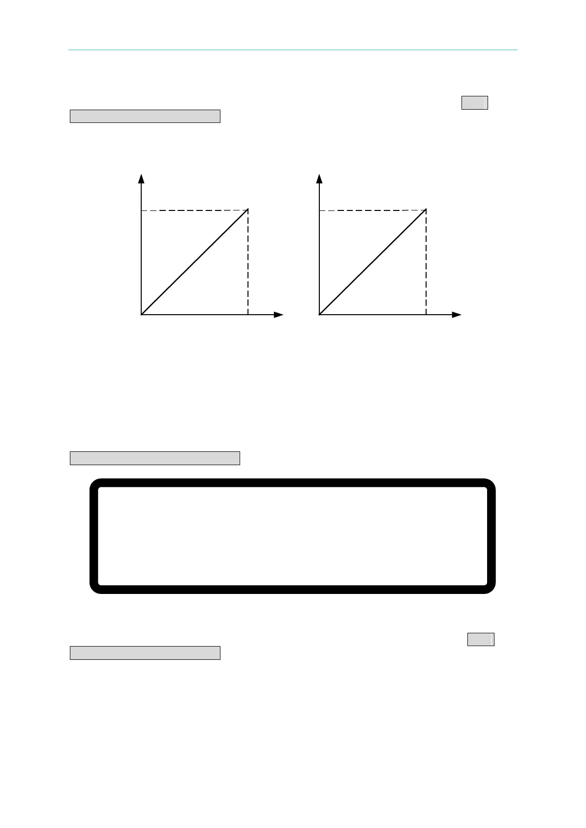
The external analog voltage 0-5V maps to the actual output voltage (0-1200V) and the actual
output current (0-25A) as shown in Figure 3-57(a). When the APG option is set to APG
VSET/APG ISET = Vref(0-10V) the external analog voltage 0-10V maps to the actual output
voltage (0-1200V) and the actual output current (0-25A) as shown in Figure 3-57(b). The
analog voltage signal wire needs to be routed through the APG interface connectors in series
in APG mode.
APG INPUT 5V/5V
DC SOURCE OUTPUT
1200V/25A
APG INPUT 10V/10V
DC SOURCE OUTPUT
1200V/25A
(a) (b)
Figure 3-57
3.3.3.6.2 Parallel Setting
The MAIN PAGE menu of the MASTER unit will display the following screen when connecting
five 62150H-600S DC Power Supplies for parallel operation and setting the APG option to
APG VSET/APG ISET = Vref(0-5V):
Figure 3-58
The external analog voltage 0-5V maps to the actual output voltage (0-600V) and the actual
output current (0-125A) as shown in Figure 3-59(a). When the APG option is set to APG
VSET/APG ISET = Vref(0-10V) the external analog voltage 0-10V maps to the actual output
voltage (0-600V) and the actual output current (0-125A) as shown in Figure 3-59(b). The
analog voltage signal wire needs to be routed through the APG interface connectors in series
in APG mode.
V = 6 0 0 .
0 0 _ V
∑ I = 1 2 5. 0 0 A M S T O F F
0 . 0 0 0 0 V
0 . 0 0 0 0 A
0 . 0
W
A P G – V S A P G – I S