6.3.7.7.- Display of variables
This parameter occupies 1 register.
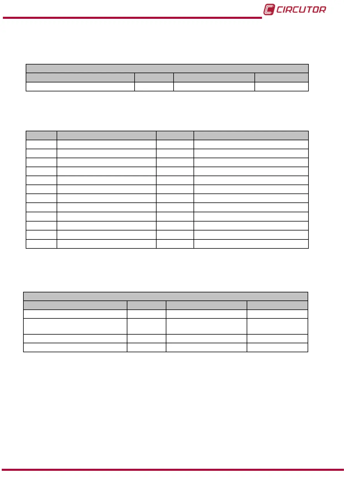
Table 37:Modbus memory map: Conguration variables (Display of variables).
Selection of variables to be displayed
Configuration variable Address Valid data window Default value
Selection of variables to be displayed 2A94 – 2A95 0x00FF FFFF
(1)
0x00FF 0xFFFF
(1)
Each variable bit indicates the display (1) or not (0) of a parameter, see Table 38, where Bit 0 is the lowest bit
and bit 32 the highest.
The variable can never have a value of 0x0000 0000; one parameter must at least be displayed. The unit will
return a frame error if this happens.
Table 38: Display of variables (List of parameters)
Bit Description Address Valid data window
0 Phase-Neutral Voltage 12
Current THD
1 Phase-Phase Voltage 13
Active Energy
2 Current 14
Inductive Reactive Energy
3
Frequency 15 Capacitive Reactive Energy
4
Active power 16 Total Reactive Energy
5
Inductive Reactive Power 17 Apparent Energy
6
Capacitive Reactive Power 18 No. hours of active tariff
7
Total Reactive Power 19
CO
2
Emissions
8
Apparent Power 20
Cost
9
Power Factor 21 Maximum current demand
10
Cosine
φ
22 Maximum active power Demand
11
Voltage THD 23 Maximum apparent power demand
6.3.7.8.- Demand
These parameters occupy 1 register each.
Table 39:Modbus memory map: Conguration variables (Maximum Demand)
Maximum Demand
Configuration variable Address Valid data window Default value
Integration time (in minutes) 274C 1 – 60 15
Type of integration 274D
0 : Scrolling window
1 : Fixed Window
0
Synchronisation 274E 0 : Internal 0
Input 274F 0 : Input 1 0
Note: The 4 registers must be written at once (as a group), otherwise it will respond with an
error.
191
Instruction Manual
CVM-B100 - CVM-B150