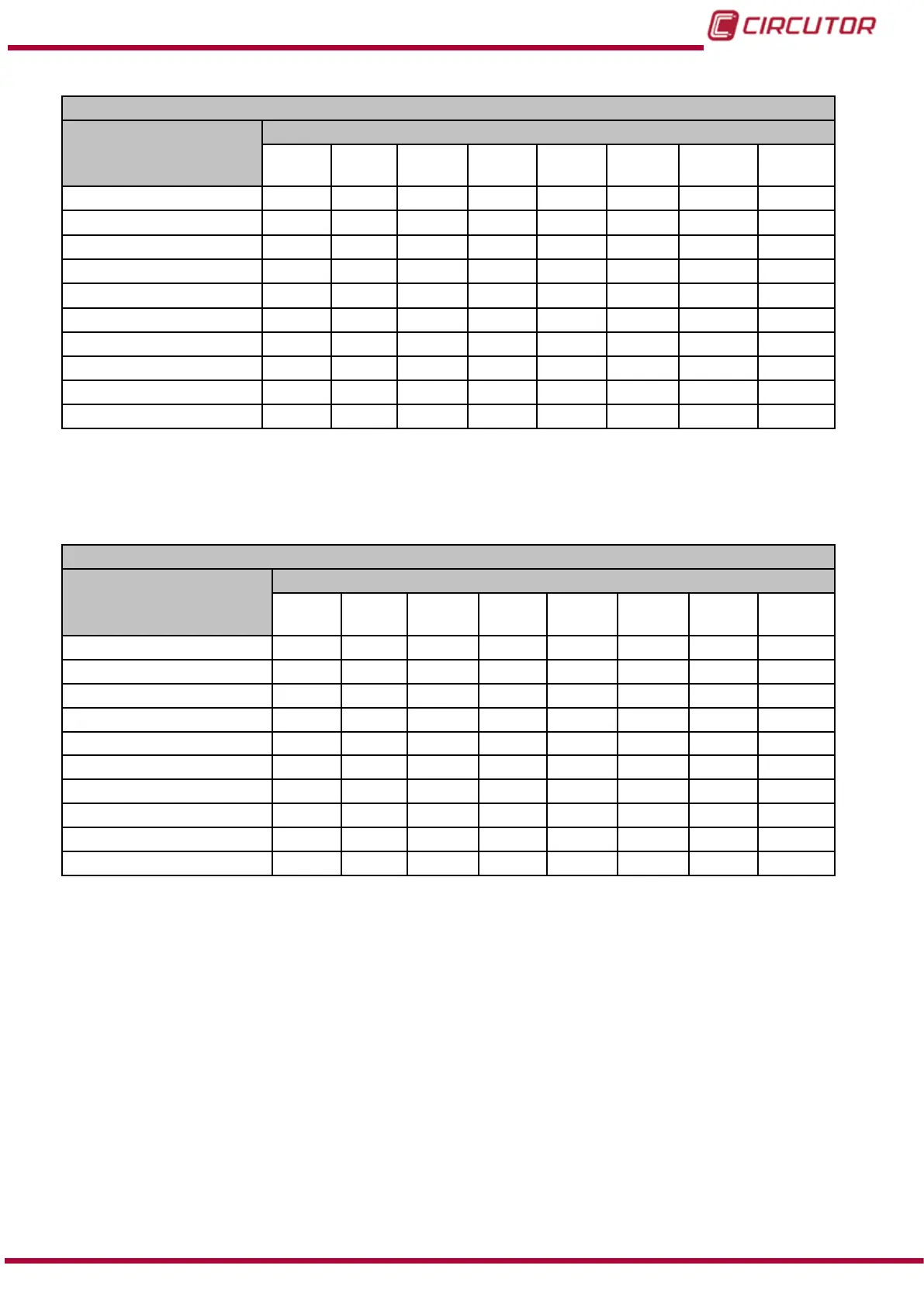
Table 70: Modbus memory map: Relay digital outputs, expansion modules (Table 3).
Conguration of the relay digital outputs : Slot 2
Configuration variable
Address
Output
1
Output
2
Output
3
Output
4
Output
5
Output
6
Output
7
Output
8
Maximum value
C738 C74C C760 C774 C788 C79C C7B0 C7C4
Minimum value
C73A C74E C762 C776 C78A C79E C7B2 C7C6
Delay connection (ON)
C73C C750 C764 C778 C78C C7A0 C7B4 C7C8
Disconnection delay (OFF)
C73D C751 C765 C779 C78D C7A1 C7B5 C7C9
Pre-alarm value C73E C752 C766 C77A C78E C7A2 C7B6 C7CA
Output status C73F C753 C767 C77B C78F C7A3 C7B7 C7CB
Latch C740 C754 C768 C77C C790 C7A4 C7B8 C7CC
Not used C741 C755 C769 C77D C791 C7A5 C7B9 C7CD
Variable code
C742 C756 C76A C77E C792 C7A6 C7BA C7CE
Module no. C743 C757 C76B C77F C793 C7A7 C7BB C7CF
Note: The 12 registers must be written and read at once (as a group), otherwise it will respond
with an error.
Table 71:Modbus memory map: Relay digital outputs, expansion modules (Table 4).
Conguration of the relay digital outputs: Slot 3
Configuration variable
Address
Output
1
Output
2
Output
3
Output
4
Output
5
Output
6
Output
7
Output
8
Maximum value
CB20 CB34 CB48 CB5C CB70 CB84 CB98 CBAC
Minimum value
CB22 CB36 CB4A CB5E CB72 CB86 CB9A CBAE
Delay connection (ON)
CB24 CB38 CB4C CB60 CB74 CB88 CB9C CBB0
Disconnection delay (OFF)
CB25 CB39 CB4D CB61 CB75 CB89 CB9D CBB1
Pre-alarm value CB26 CB3A CB4E CB62 CB76 CB8A CB9E CBB2
Output status CB27 CB3B CB4F CB63 CB77 CB8B CB9F CBB3
Latch CB28 CB3C CB50 CB64 CB78 CB8C CBA0 CBB4
Not used CB29 CB3D CB51 CB65 CB79 CB8D CBA1 CBB5
Variable code
CB2A CB3E CB52 CB66 CB7A CB8E CBA2 CBB6
Module no. CB2B CB3F CB53 CB67 CB7B CB8F CBA3 CBB7
Note: The 12 registers must be written and read at once (as a group), otherwise it will respond
with an error.
221
Instruction Manual
CVM-B100 - CVM-B150