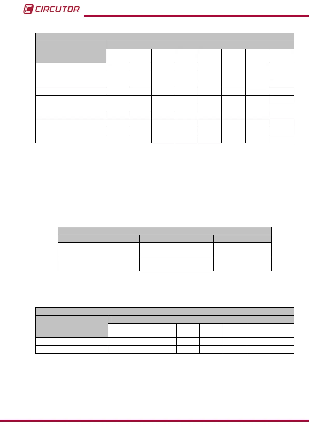
Table 72:Modbus memory map: Relay digital outputs, expansion modules (Table 5).
Conguration of relay digital outputs: Slot 4
Configuration variable
Address
Output
1
Output
2
Output
3
Output
4
Output
5
Output
6
Output
7
Output
8
Maximum value
CF08 CF1C CF30 CF44 CF58 CF6C CF80 CF94
Minimum value
CF0A CF1E CF32 CF46 CF5A CF6E CF82 CF96
Delay connection (ON)
CF0C CF20 CF34 CF48 CF5C CF70 CF84 CF98
Disconnection delay (OFF)
CF0D CF21 CF35 CF49 CF5D CF71 CF85 CF99
Pre-alarm value CF0E CF22 CF36 CF4A CF5E CF72 CF86 CF9A
Output status CF0F CF23 CF37 CF4B CF5F CF73 CF87 CF9B
Latch CF10 CF24 CF38 CF4C CF60 CF74 CF88 CF9C
Not used CF11 CF25 CF39 CF4D CF61 CF75 CF89 CF9D
Variable code
CF12 CF26 CF3A CF4E CF62 CF76 CF8A CF9E
Module no. CF13 CF27 CF3B CF4F CF63 CF77 CF8B CF9F
Note: The 12 registers must be written and read at once (as a group), otherwise it will respond
with an error.
7.2.4.2.- Manual programming of relay digital outputs
The following functions are implemented for these variables:
Function 0x04: reading registers.
Function 0x10: Writing multiple registers.
Table 73: Modbus memory map: Manual programming of outputs, expansion modules (Table 1).
Manual programming of relay digital outputs
Configuration variable Valid data window Default value
Programming status
(1)
0: Automatic
1:Manual
0
Value
0: Open
1:Closed
0
(1)
When programming the Programming status manually set the output for the relays manually, using the Value
parameter. The conguration of the relay digital outputs programmed in the unit no longer works.
The relays work in automatic mode according to the conguration programmed in the unit.
Table 74: Modbus memory map: Manual programming of outputs, expansion modules (Table 2).
Manual programming of relay digital outputs: Slot 1
Configuration variable
Address
Output
1
Output
2
Output
3
Output
4
Output
5
Output
6
Output
7
Output
8
Programming status C428
C43C C450 C464 C478 C48C C4A0 C4B4
Value
C429
C43D C451 C465 C479 C48D C4A1 C4B5
Note: The 2 registers must be written at once (as a group), otherwise it will respond with an
error.
222
CVM-B100 - CVM-B150
Instruction Manual