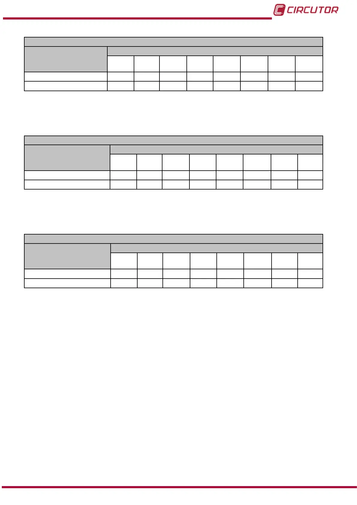
Table 75: Modbus memory map: Manual programming of outputs, expansion modules (Table 3).
Manual programming of relay digital outputs: Slot 2
Configuration variable
Address
Output
1
Output
2
Output
3
Output
4
Output
5
Output
6
Output
7
Output
8
Programming status C810
C824 C838 C84C C874 C874 C888 C89C
Value
C811
C825 C839 C84D C875 C875 C889 C89D
Note: The 2 registers must be written at once (as a group), otherwise it will respond with an
error.
Table 76: Modbus memory map: Manual programming of outputs, expansion modules (Table 4).
Manual programming of relay digital outputs: Slot 3
Configuration variable
Address
Output
1
Output
2
Output
3
Output
4
Output
5
Output
6
Output
7
Output
8
Programming status CBF8
CC0C CC20 CC34 CC48 CC5C CC70 CC84
Value
CBF9
CC0d CC21 CC35 CC49 CC5D CC71 CC85
Note: The 2 registers must be written at once (as a group), otherwise it will respond with an
error.
Table 77: Modbus memory map: Manual programming of outputs, expansion modules (Table 5).
Manual programming of relay digital outputs: Slot 4
Configuration variable
Address
Output
1
Output
2
Output
3
Output
4
Output
5
Output
6
Output
7
Output
8
Programming status CFE0
CFF4 D008 D01C D030 D044 D058 D06C
Value
CFE1
CFF5 D009 D01D D031 D045 D059 D06D
Note: The 2 registers must be written at once (as a group), otherwise it will respond with an
error.
7.2.4.3.- Programming the digital inputs
The Modbus memory map for the digital inputs of the relay digital inputs/outputs module is the
same as the transistor digital inputs/outputs module, see “7.3.4.3.- Programming the digital
inputs”
7.2.4.4.- Status of digital inputs
The Modbus memory map for the status of the digital inputs of the relay digital inputs/outputs
module is the same as the transistor digital inputs/outputs module, see “7.3.4.4.- Status of digital
inputs”
223
Instruction Manual
CVM-B100 - CVM-B150