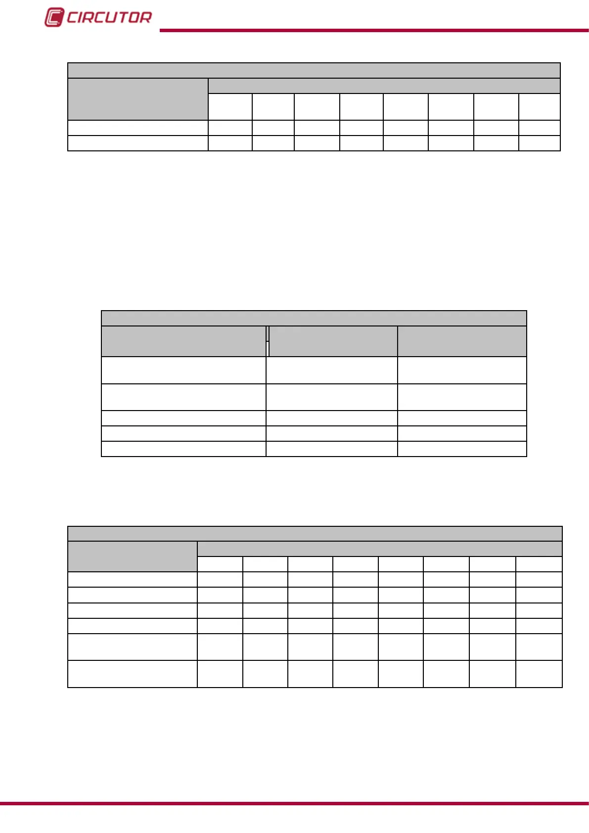
Table 94: Modbus memory map: Manual programming of outputs, expansion modules (Table 5).
Manual programming of transistor digital outputs: Slot 4
Configuration variable
Address
Output
1
Output
2
Output
3
Output
4
Output
5
Output
6
Output
7
Output
8
Programming status CFE0
CFF4 D008 D01C D030 D044 D058 D06C
Value
CFE1
CFF5 D009 D01D D031 D045 D059 D06D
Note: The 2 registers must be written at once (as a group), otherwise it will respond with an
error.
7.3.4.3.- Programming the digital inputs
The following functions are implemented for these variables:
Function 0x04: reading registers.
Function 0x10: Writing multiple registers.
Table 95:Modbus memory map: Digital inputs, expansion modules (Table 1).
Conguration of Digital Inputs
Configuration variable Valid data window Default value
Mode
0: Logic state
> 0:Impulses
(1)
0
Logic (Logic state)
0: positive
1: Negative
0
Input name (impulses)
(2)
8 characters “INPUT”
Units (Impulses)
(2)
6 characters -
No. of decimals (Impulses) 0 to 5
0
(1)
When programming a value of more than 1, program the impulse operating mode and energy meter factor for
this mode simultaneously.
(2)
the characters must be sent in hexadecimal.
Table 96: Modbus memory map: Digital inputs, expansion modules (Table 2).
Conguration of digital inputs: Slot 1
Configuration variable
Address
Input 1 Input 2 Input 3 Input 4 Input 5 Input 6 Input 7 Input 8
Mode
C4E0
C4EC C4F8 C504 C510 C51C C528 C534
Logic (Logic state)
C4E1
C4ED C4F9 C505 C511 C51D C529 C535
No. of decimals (Impulses) C4E2
C4EE C4FA C506 C512 C51E C52A C536
Not used
C4E3
C4EF C4FB C507 C513 C51F C52B C537
Input name (impulses)
C4E4 -
C4E7
C4F0-
C4F3
C4FC-
C4FF
C508-
C50B
C514-
C517
C520-
C523
C52C-
C52F
C538-
C53B
Units (Impulses)
C4E8 -
C4EA
C4F4-
C4F6
C500-
C502
C50C-
C50E
C518-
C51A
C524-
C526
C530
C532
C53C
C53E
Note: The 11 registers must be written and read at once (as a group), otherwise it will respond
with an error.
236
CVM-B100 - CVM-B150
Instruction Manual