7.3.4.2.- Manual programming of transistor digital outputs
The following functions are implemented for these variables:
Function 0x04:reading registers.
Function 0x10: Writing multiple registers.
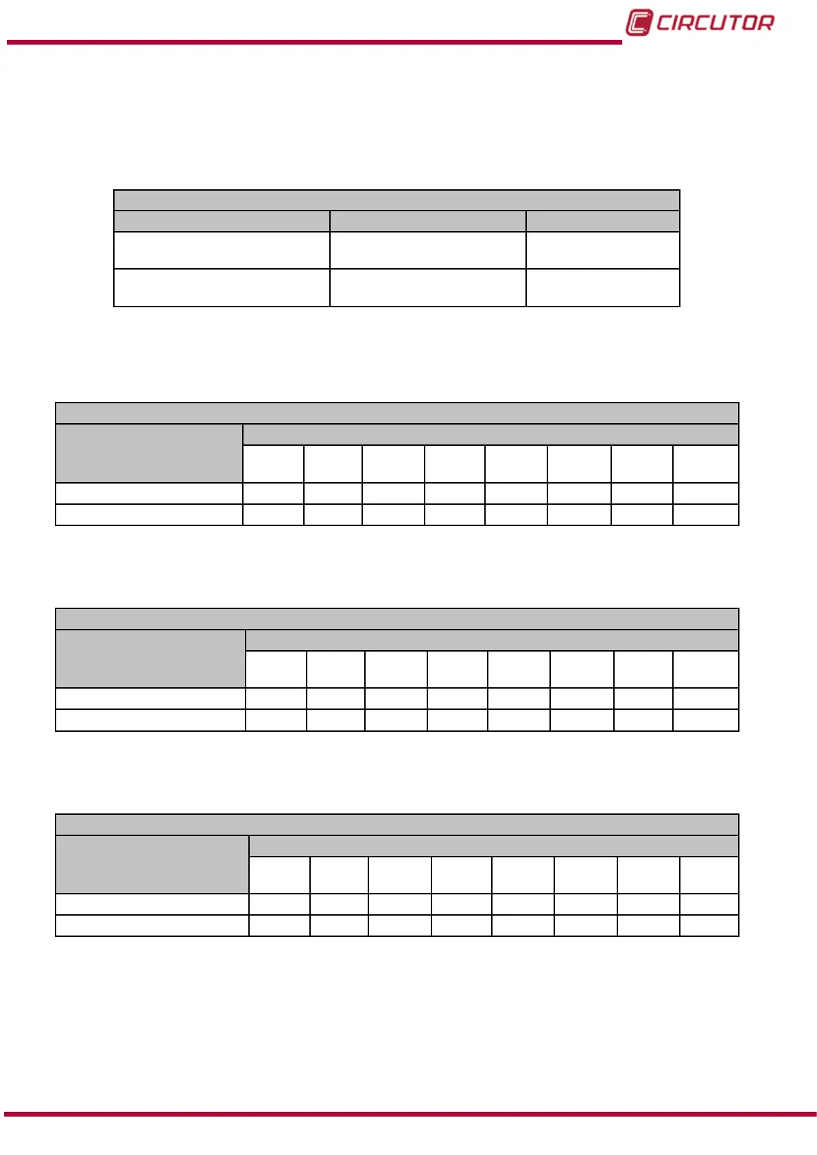
Table 90: Modbus memory map: Manual programming of outputs, expansion modules (Table 1).
Manual programming of transistor digital outputs
Configuration variable Valid data window Default value
Programming status
(1)
0: Automatic
1:Manual
0
Value
0: Open
1:Closed
0
(1)
When programming the Programming status manually set the output for the transistors manually, using the
Value parameter. The conguration of the transistor digital outputs programmed in the unit no longer works.
The transistors work in automatic mode according to the conguration programmed in the unit.
Table 91: Modbus memory map: Manual programming of outputs, expansion modules (Table 2).
Manual programming of transistor digital outputs: Slot 1
Configuration variable
Address
Output
1
Output
2
Output
3
Output
4
Output
5
Output
6
Output
7
Output
8
Programming status C428
C43C C450 C464 C478 C48C C4A0 C4B4
Value
C429
C43D C451 C465 C479 C48D C4A1 C4B5
Note: The 2 registers must be written at once (as a group), otherwise it will respond with an
error.
Table 92: Modbus memory map: Manual programming of outputs, expansion modules (Table 3).
Manual programming of transistor digital outputs: Slot 2
Configuration variable
Address
Output
1
Output
2
Output
3
Output
4
Output
5
Output
6
Output
7
Output
8
Programming status C810
C824 C838 C84C C874 C874 C888 C89C
Value
C811
C825 C839 C84D C875 C875 C889 C89D
Note: The 2 registers must be written at once (as a group), otherwise it will respond with an
error.
Table 93: Modbus memory map: Manual programming of outputs, expansion modules (Table 4).
Manual programming of transistor digital outputs: Slot 3
Configuration variable
Address
Output
1
Output
2
Output
3
Output
4
Output
5
Output
6
Output
7
Output
8
Programming status CBF8
CC0C CC20 CC34 CC48 CC5C CC70 CC84
Value
CBF9
CC0d CC21 CC35 CC49 CC5D CC71 CC85
Note: The 2 registers must be written at once (as a group), otherwise it will respond with an
error.
235
Instruction Manual
CVM-B100 - CVM-B150