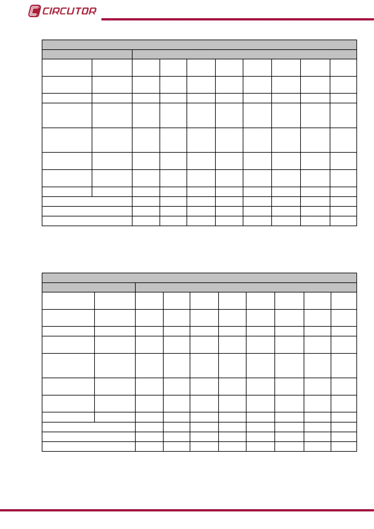
Table 88: Modbus memory map: Transistor digital outputs, expansion modules (Table 4).
Transistor Digital Outputs conguration: Slot 3
Configuration variable Address
Alarm
Impulse
output
Output
1
Output
2
Output
3
Output
4
Output
5
Output
6
Output
7
Output
8
Maximum value
Energy
meter factor
CB20 CB34 CB48 CB5C CB70 CB84 CB98 CBAC
Minimum value -
CB22 CB36 CB4A CB5E CB72 CB86 CB9A CBAE
Delay in the
Connection
(ON)
High period CB24 CB38 CB4C CB60 CB74 CB88 CB9C CBB0
Delay in the
Disconnection
(OFF)
Low period CB25 CB39 CB4D CB61 CB75 CB89 CB9D CBB1
Value of
Pre-alarm
- CB26 CB3A CB4E CB62 CB76 CB8A CB9E CBB2
Status of
The output
- CB27 CB3B CB4F CB63 CB77 CB8B CB9F CBB3
Latch - CB28 CB3C CB50 CB64 CB78 CB8C CBA0 CBB4
Not used CB29 CB3D CB51 CB65 CB79 CB8D CBA1 CBB5
Variable code
CB2A CB3E CB52 CB66 CB7A CB8E CBA2 CBB6
Module no.
CB2B CB3F CB53 CB67 CB7B CB8F CBA3 CBB7
Note: The 12 registers must be written and read at once (as a group), otherwise it will respond
with an error.
Table 89: Modbus memory map: Transistor digital outputs, expansion modules (Table 5).
Transistor Digital Outputs conguration: Slot 4
Configuration variable Address
Alarm
Impulse
output
Output
1
Output
2
Output
3
Output
4
Output
5
Output
6
Output
7
Output
8
Maximum value
Energy
meter factor
CF08 CF1C CF30 CF44 CF58 CF6C CF80 CF94
Minimum value -
CF0A CF1E CF32 CF46 CF5A CF6E CF82 CF96
Delay in the
Connection (ON)
High period CF0C CF20 CF34 CF48 CF5C CF70 CF84 CF98
Delay in the
Disconnection
(OFF)
Low period CF0D CF21 CF35 CF49 CF5D CF71 CF85 CF99
Value of
Pre-alarm
- CF0E CF22 CF36 CF4A CF5E CF72 CF86 CF9A
Status of
The output
- CF0F CF23 CF37 CF4B CF5F CF73 CF87 CF9B
Latch - CF10 CF24 CF38 CF4C CF60 CF74 CF88 CF9C
Not used CF11 CF25 CF39 CF4D CF61 CF75 CF89 CF9D
Variable code
CF12 CF26 CF3A CF4E CF62 CF76 CF8A CF9E
Module no.
CF13 CF27 CF3B CF4F CF63 CF77 CF8B CF9F
Note: The 12 registers must be written and read at once (as a group), otherwise it will respond
with an error.
234
CVM-B100 - CVM-B150
Instruction Manual