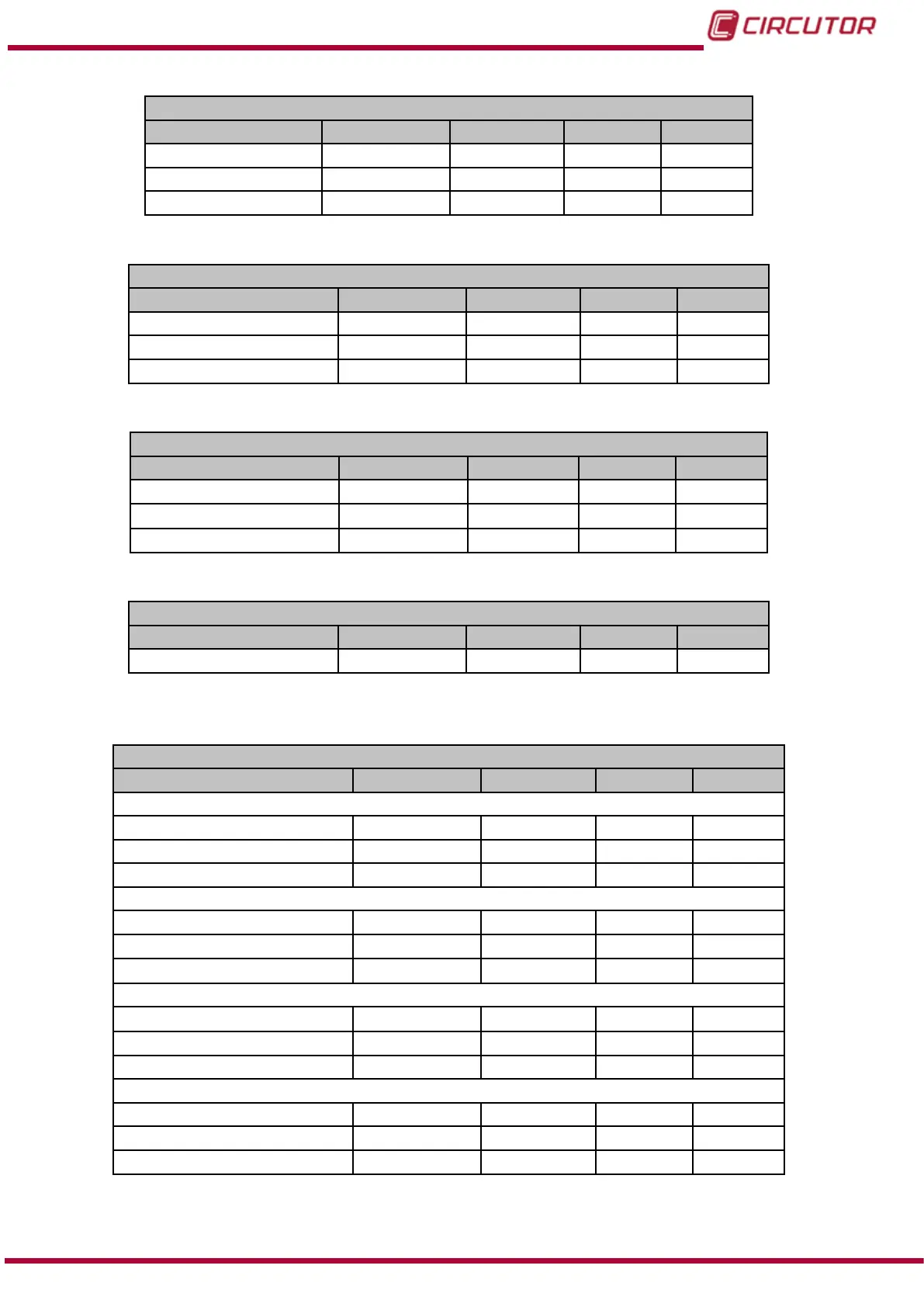
Table 138: GSD modules (Module 1 - Mod 1.2)
Mod 1.2
Phase currents Symbol Bytes Address Units
Current A 1 4 02-03 mA
Current A 2 4 12-13 mA
Current A 3 4 22-23 mA
Table 139: GSD modules (Module 1 - Mod 1.3)
Mod 1.3
Phase-phase voltage Symbol Bytes Address Units
Line voltage L1-L2 V 12 4 36-37 Vx100
Line voltage L2-L3 V 23 4 38-39 Vx100
Line voltage L3-L1 V 31 4 3A-3B Vx100
Table 140: GSD modules (Module 1 - Mod 1.4)
Mod 1.4
Power factor Symbol Bytes Address Units
Power factor PF 1 4 0C-0D x100
Power factor PF 2 4 1C-1D x100
Power factor PF 3 4 2C-2D x100
Table 141: GSD modules (Module 1 - Mod 1.5)
Mod 1.5
Frequency Symbol Bytes Address Units
Frequency (L1) Hx 4 34-35 Hz x100
Module 2
Table 142: GSD modules (Module 2)
Mod 2
Powers Symbol Bytes Address Units
Active powers
Active power Kw 1 4 04-05 W
Active power Kw 2 4 14-15 W
Active power Kw 3 4 24-25 W
Inductive reactive powers
Inductive reactive power KvarL 1 4 06-07 var
Inductive reactive power KvarL 2 4 16-17 var
Inductive reactive power KvarL 3 4 26-27 var
Capacitive reactive powers
Capacitive reactive power KvarC 1 4 08-09 var
Capacitive reactive power KvarC 2 4 18-19 var
Capacitive reactive power KvarC 3 4 28-29 var
Apparent power
Apparent power kVA1 4 0A-0B VA
Apparent power kVA2 4 1A-1B VA
Apparent power kVA3 4 2A-2B VA
285
Instruction Manual
CVM-B100 - CVM-B150