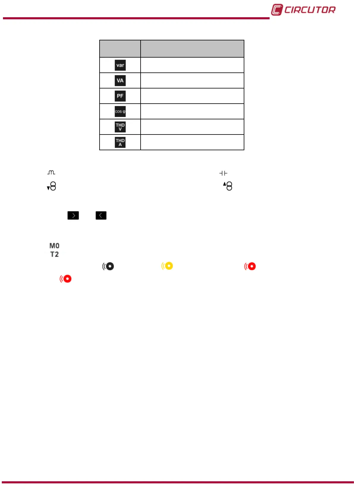
Table 8 ( Continuation) : Instantaneous parameters.
Icon
Display 1 parameter
Instantaneous parameters
Total reactive power
(1)
Apparent power
(1)
Power factor
(1)
Cosine phi III
(1)
Voltage THD
(1)
Current THD
(1)
(1)
The following icons appear for all these parameters on the screen:
Indicating that the parameter refers to inductive or capacitive energy.
Indicating that the parameter refers to consumed or generated energy.
If the 2 icons light up at the same time, it means the installation is not properly connected.
Use the keys
and to browse the various parameters.
If there is an alarm associated with the variable being displayed, the following will be shown:
The module with which the alarm is associated.
The associated output in the module.
The alarm status: not activated, pre-alarm activated, alarm activated.
The icon flashes during the delay time in the alarm connection (ON) and
disconnection (OFF).
The menu in the lower area disappears after 3 seconds (
Figure 30).
41
Instruction Manual
CVM-B100 - CVM-B150