1-15
Catalyst 3750-X and 3560-X Switch Software Configuration Guide
OL-25303-03
Chapter 1 Clustering Switches
Planning a Switch Cluster
Recall that stack members work together to behave as a unified system (as a single switch stack) in the
network and are presented to the network as such by Layer 2 and Layer 3 protocols. Therefore, the
switch cluster recognizes switch stacks, not individual stack members, as eligible cluster members.
Individual stack members cannot join a switch cluster or participate as separate cluster members.
Because a switch cluster must have 1 cluster command switch and can have up to 15 cluster members, a
cluster can potentially have up to 16 switch stacks, totalling 144 devices.
Cluster configuration of switch stacks is through the stack master.
These are considerations to keep in mind when you have switch stacks in switch clusters:
• If the cluster command switch is not a Catalyst 3750-E switch or switch stack and a new stack
master is elected in a cluster member switch stack, the switch stack loses its connectivity to the
switch cluster if there are no redundant connections between the switch stack and the cluster
command switch. You must add the switch stack to the switch cluster.
• If the cluster command switch is a switch stack and new stack masters are simultaneously elected in
the cluster command switch stack and in cluster member switch stacks, connectivity between the
switch stacks is lost if there are no redundant connections between the switch stack and the cluster
command switch. You must add the switch stacks to the cluster, including the cluster command
switch stack.
• All stack members should have redundant connectivity to all VLANs in the switch cluster.
Otherwise, if a new stack master is elected, stack members connected to any VLANs not configured
on the new stack master lose their connectivity to the switch cluster. You must change the VLAN
configuration of the stack master or the stack members and add the stack members back to the switch
cluster.
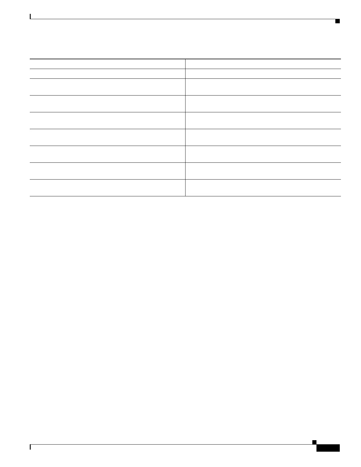
Can be a cluster command switch or a cluster member switch Cannot be a stack master or stack member
Stack master is the single point of complete management for
all stack members in a particular switch stack
Cluster command switch is the single point of some manage-
ment for all cluster members in a particular switch cluster
Back-up stack master is automatically determined in case the
stack master fails
Standby cluster command switch must be pre-assigned in case
the cluster command switch fails
Switch stack supports up to eight simultaneous stack master
failures
Switch cluster supports only one cluster command switch
failure at a time
Stack members (as a switch stack) behave and is presented as
a single, unified system in the network
Cluster members are various, independent switches that are
not managed as and do not behave as a unified system
Integrated management of stack members through a single
configuration file
Cluster members have separate, individual configuration files
Stack- and interface-level configurations are stored on each
stack member
Cluster configuration are stored on the cluster command
switch and the standby cluster command switch
New stack members are automatically added to the switch
stack
New cluster members must be manually added to the switch
cluster
Table 1-2 Basic Comparison of Switch Stacks and Switch Clusters (continued)
Switch Stack Switch Cluster