1-8
Catalyst 3750-X and 3560-X Switch Software Configuration Guide
OL-25303-03
Chapter 1 Clustering Switches
Planning a Switch Cluster
Note If the switch cluster has a Catalyst 3750-E or Catalyst 3750-X switch or switch stack, that switch or
switch stack must be the cluster command switch.
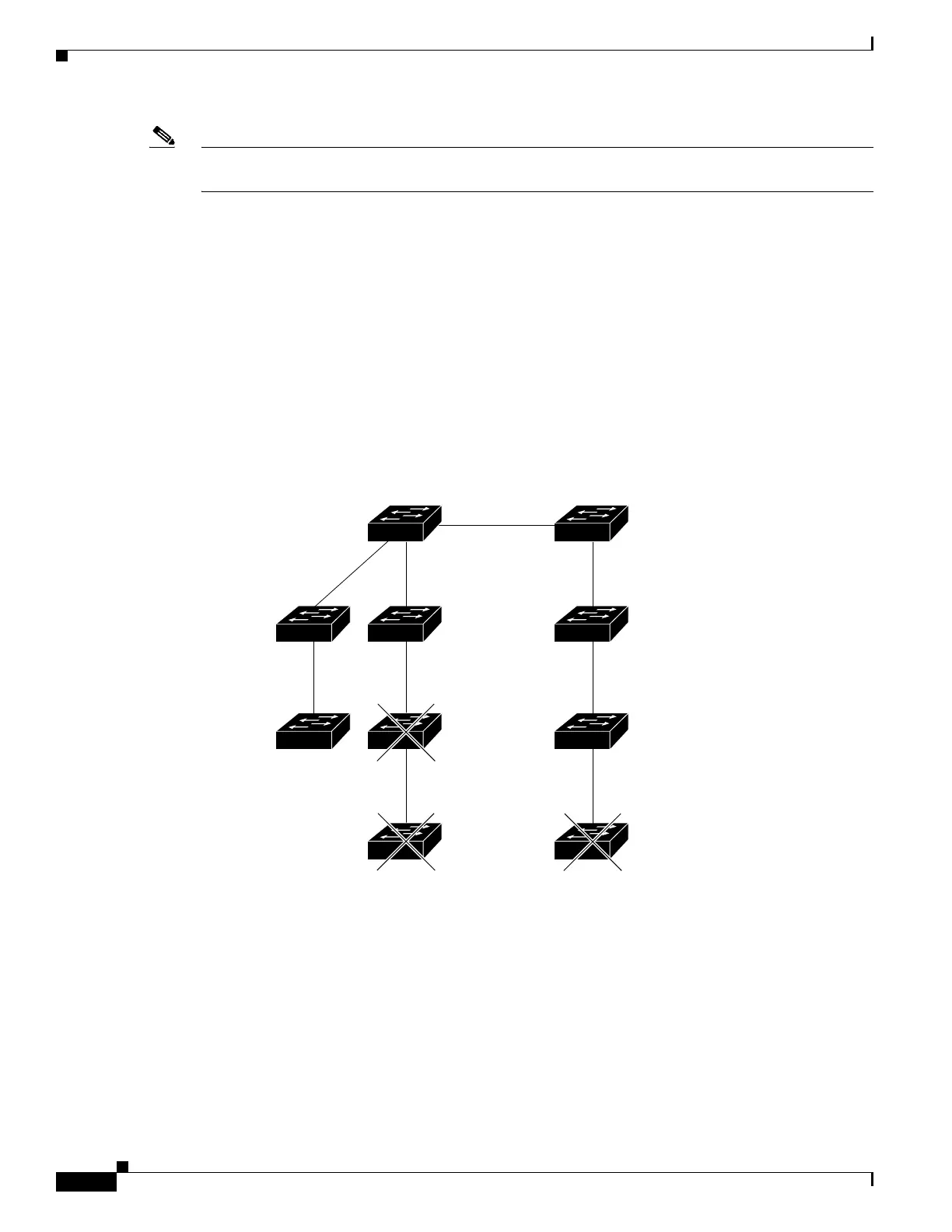
The cluster command switch and standby command switch in Figure 1-4 (assuming they are
Catalyst 2960 Catalyst 2970, Catalyst 3550, Catalyst 3560, Catalyst 3560-E, Catalyst 3750,
Catalyst 3750-E, Catalyst 3560-X, or Catalyst 3750-X cluster command switches) have ports assigned
to VLANs 9, 16, and 62. The management VLAN on the cluster command switch is VLAN 9. Each
cluster command switch discovers the switches in the different management VLANs except these:
• Switches 7 and 10 (switches in management VLAN 4) because they are not connected through a
common VLAN (meaning VLANs 62 and 9) with the cluster command switch
• Switch 9 because automatic discovery does not extend beyond a noncandidate device, which is
switch 7
Figure 1-4 Discovery Through Different Management VLANs with a Layer 3 Cluster Command
Switch
Discovery Through Routed Ports
If the cluster command switch has a routed port (RP) configured, it discovers only candidate and cluster
member switches in the same VLAN as the routed port. For more information about routed ports, see the
“Routed Ports” section on page 1-4.
The Layer 3 cluster command switch in Figure 1-5 can discover the switches in VLANs 9 and 62 but not
the switch in VLAN 4. If the routed port path between the cluster command switch and cluster member
switch 7 is lost, connectivity with cluster member switch 7 is maintained because of the redundant path
through VLAN 9.
101323
VLAN 62
VLAN trunk 4, 62
VLAN 62
VLAN 16
VLAN 9
VLAN 16
VLAN 9
Standby command
device
Command
device
VLAN 9
Device 7
(management
VLAN 4)
Device 9
(management
VLAN 62)
VLAN 4
Device 3
(management
VLAN 16)
Device 4
(management
VLAN 16)
Device 10
(management
VLAN 4)
Device 8
(management
VLAN 9)
Device 6
(management
VLAN 9)
Device 5
(management
VLAN 62)