13-45
Catalyst 3750-X and 3560-X Switch Software Configuration Guide
OL-21521-01
Chapter 13 Configuring Interface Characteristics
Monitoring and Maintaining the Interfaces
Monitoring and Maintaining the Interfaces
These sections contain interface monitoring and maintenance information:
• Monitoring Interface Status, page 13-45
• Clearing and Resetting Interfaces and Counters, page 13-46
• Shutting Down and Restarting the Interface, page 13-47
Monitoring Interface Status
Commands entered at the privileged EXEC prompt display information about the interface, including
the versions of the software and the hardware, the configuration, and statistics about the interfaces.
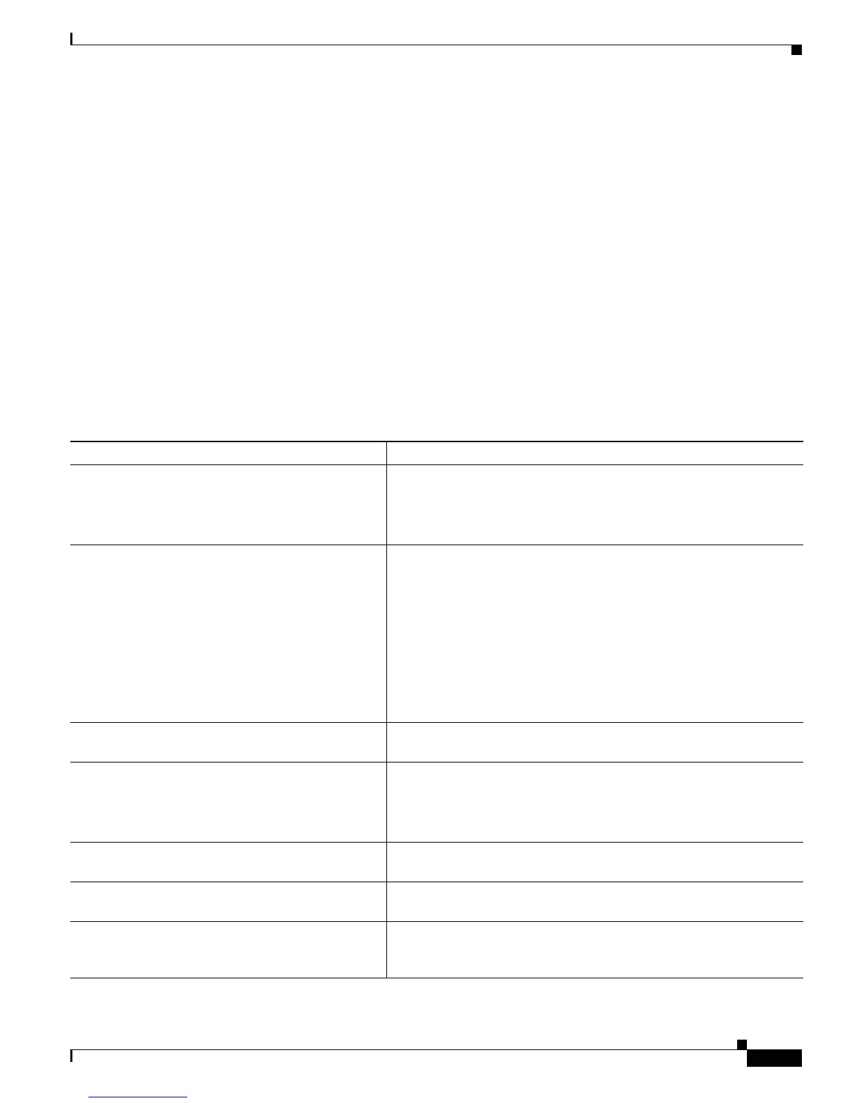
Table 13-6 lists some of these interface monitoring commands. (You can display the full list of sho
w
commands by using the sho
w ? command at the privileged EXEC prompt.) These commands are fully
described in the Cisco IOS Interface Command Reference, Release 12.2.
Ta ble 13-6 Show Commands for Interfaces
Command Purpose
show env power switch [swi
tch-number] (Optional) Display the status of the internal power supplies for each
switch in the stack or for the specified switch. The range is 1 to 9,
depending on the switch member numbers in the stack.
These keywords are available only on Catalyst 3750-E switches.
show env rps Display whether a redundant power system
(RPS) is connected to the
switch as follows:
–
Catalyst 3750-E or 3560-E switch—Cisco Redundant Power
System 2300, also referred to as the RPS 2300.
–
Catalyst 3750v2 or 3560v2 switch—Cisco Redundant Power
System 2300.
–
Catalyst 3750, 3560, 2970, or 2960 switches—RPS 2300 or
Cisco RPS 675 Redundant Power System, also referred to as
the RPS 675.
show env rp
s detail (Optional) Display the details about the RPSs that are connected to the
switch or switch stack.
show env rps switch [switc
h-number] (Optional) Display the RPSs that are connected to each switch in the
stack or to the specified switch. The range is 1 to 9, depending on the
switch member numbers in the stack.
show interfaces [in
terface-id] Display the status and configuration of all interfaces or a specific
interface.
show interfaces in
terface-id status [err-disabled] Display interface status or a list of interfaces in the error-disabled
state.
show interfaces [in
terface-id] switchport Display administrative and operational status of switching
(nonrouting) ports. You can use this command to find out if a port is in
routing or in switching mode.