39-5
Catalyst 3750-X and 3560-X Switch Software Configuration Guide
OL-21521-01
Chapter 39 Configuring QoS
Understanding QoS
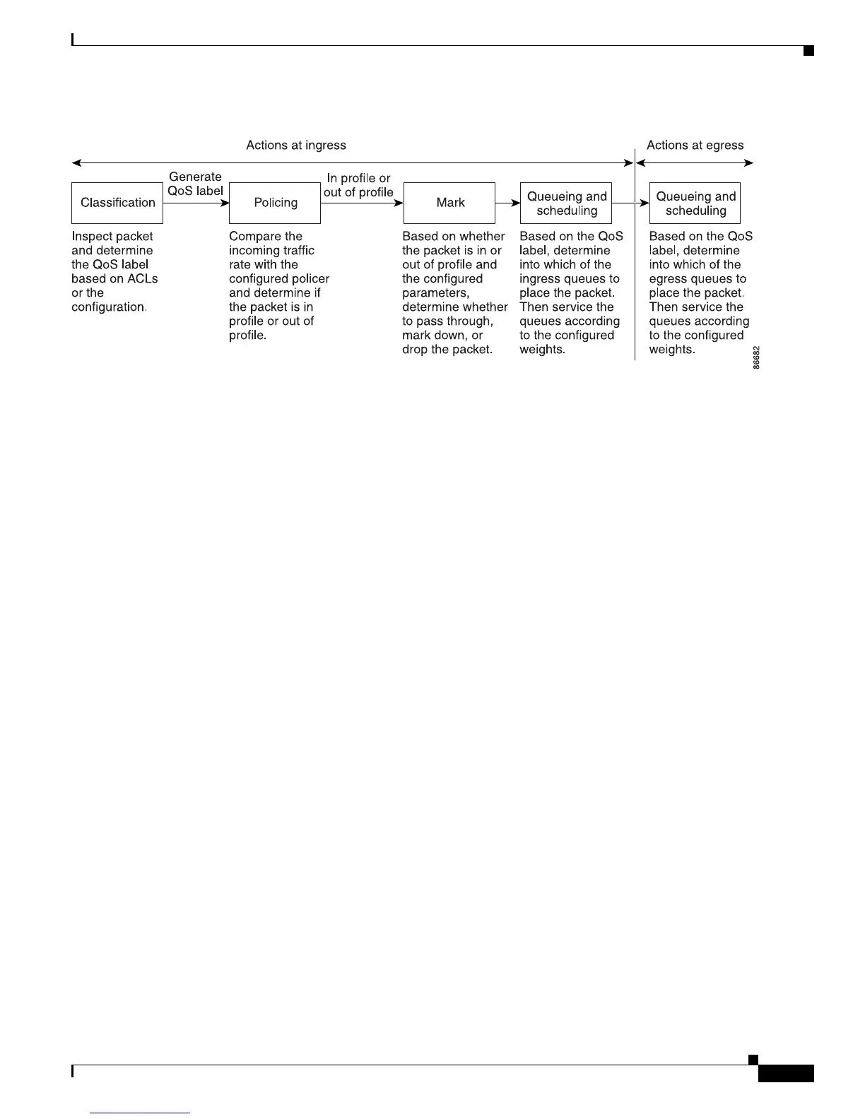
Figure 39-2 Basic QoS Model
Classification
Classification is the process of distinguishing one kind of traffic from another by examining the fields
in the packet. Classification is enabled only if QoS is globally enabled on the switch. By default, QoS is
globally disabled, so no classification occurs.
During classification, the switch performs a lookup and assigns a QoS label to the packet. The QoS label
i
dentifies all QoS actions to be performed on the packet and from which queue the packet is sent.
The QoS label is based on the DSCP or the CoS value in the pa
cket and decides the queueing and
scheduling actions to perform on the packet. The label is mapped according to the trust setting and the
packet type as shown in Figure 39-3 on page 39-7.
You specify which fields in the frame or p
acket that you want to use to classify incoming traffic. For
non-IP traffic, you have these classification options as shown in Figure 39-3:
• Trust the CoS value in the incoming frame (configure the port to trust CoS). Then use the
configurable CoS-to-DSCP map to generate a DSCP value for the packet. Layer 2 ISL frame headers
carry the CoS value in the 3 least-significant bits of the 1-byte User field. Layer 2 802.1Q frame
headers carry the CoS value in the 3 most-significant bits of the Tag Control Information field. CoS
values range from 0 for low priority to 7 for high priority.
• Trust the DSCP or trust IP precedence value in the incoming frame. These configurations are
meaningless for non-IP traffic. If you configure a port with either of these options and non-IP traffic
is received, the switch assigns a CoS value and generates an internal DSCP value from the
CoS-to-DSCP map. The switch uses the internal DSCP value to generate a CoS value representing
the priority of the traffic.
• Perform the classification based on a configured Layer 2 MAC access control list (ACL), which can
examine the MAC source address, the MAC destination address, and other fields. If no ACL is
configured, the packet is assigned 0 as the DSCP and CoS values, which means best-effort traffic.
Otherwise, the policy-map action specifies a DSCP or CoS value to assign to the incoming frame.