42-2
Catalyst 3750-X and 3560-X Switch Software Configuration Guide
OL-21521-01
Chapter 42 Configuring IP Unicast Routing
Understanding IP Routing
• Configuring Multi-VRF CE, page 42-74
• Configuring Protocol-Independent Features, page 42-89
• Monitoring and Maintaining the IP Network, page 42-104
Note When configuring routing parameters on the switch and to allocate system resources to maximize the
number of unicast routes allowed, you can use the sdm prefer routing global configuration command
to set the Switch Database Management (sdm) feature to the routing template. For more information on
the SDM templates, see Chapter 8, “Configuring SDM Templates” or see the s
dm prefer command in
the command reference for this release.
Understanding IP Routing
In some network environments, VLANs are associated with individual networks or subnetworks. In an
IP network, each subnetwork is mapped to an individual VLAN. Configuring VLANs helps control the
size of the broadcast domain and keeps local traffic local. However, network devices in different VLANs
cannot communicate with one another without a Layer 3 device (router) to route traffic between the
VLAN, referred to as inter-VLAN routing. You configure one or more routers to route traffic to the
appropriate destination VLAN.
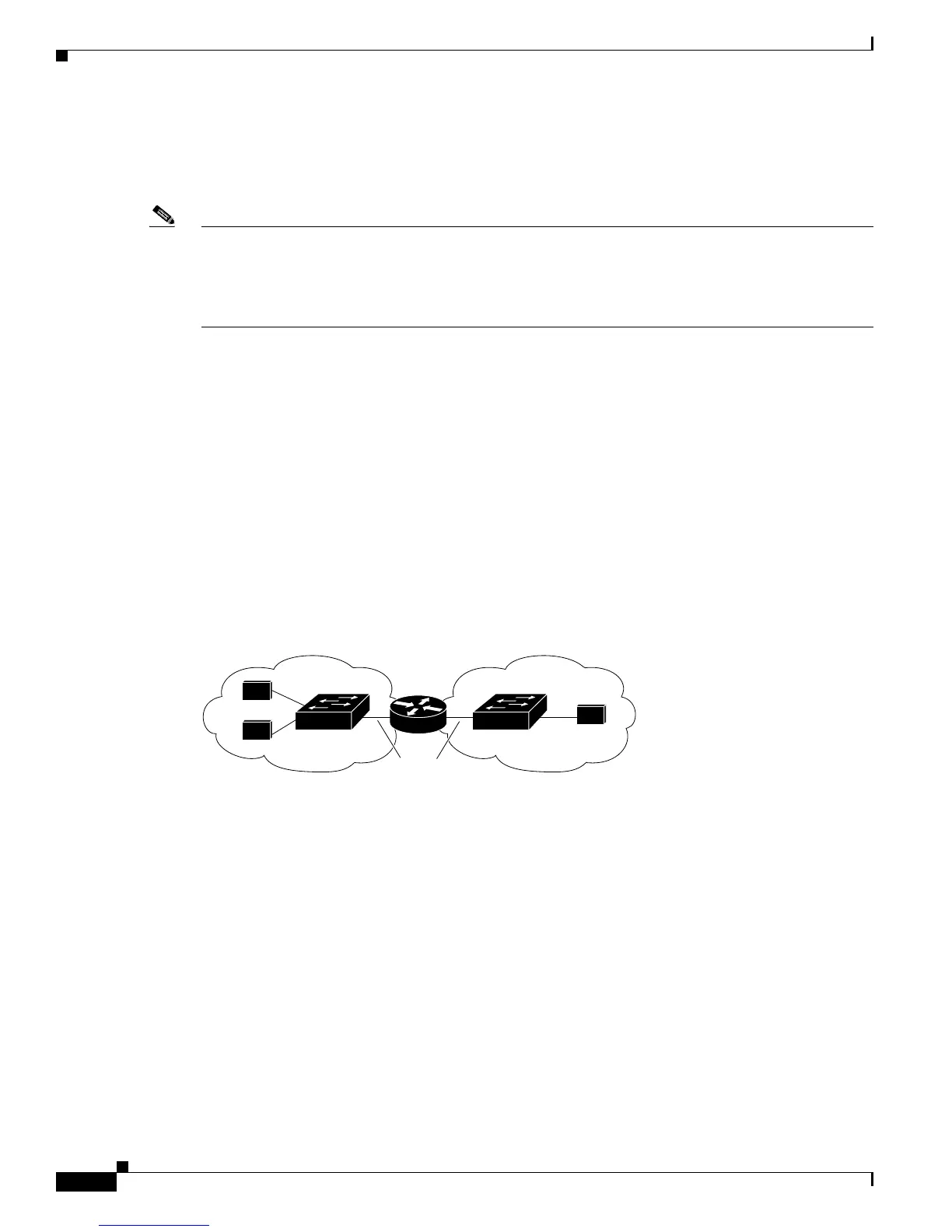
Figure 42-1 sho
ws a basic routing topology. Switch A is in VLAN 10, and Switch B is in VLAN 20. The
router has an interface in each VLAN.
Figure 42-1 Routing Topology Example
When Host A in VLAN 10 needs to communicate with Host B in VLAN 10, it sends a packet addressed
to that host. Switch A forwards the packet directly to Host B, without sending it to the router.
When Host A sends a packet to Host C in VLAN 20, Switch A forwards the packet to the router, which
rece
ives the traffic on the VLAN 10 interface. The router checks the routing table, finds the correct
outgoing interf
ace, and forwards the packet on the VLAN 20 interface to Switch B. Switch B receives
the pac
ket and forwards it to Host C.
This section contains informatio
n on these routing topics:
• Types of Routing, page 42-3
• IP Routing and Switch Stacks, page 42-3
18071
A
B
C
Host
Host
Host
Switch A Switch B
VLAN 10 VLAN 20
ISL Trunks