26-19
Catalyst 3750-X and 3560-X Switch Software Configuration Guide
OL-21521-01
Chapter 26 Configuring IGMP Snooping and MVR
Configuring MVR
Layer 3 device. The access layer switch, Switch A, modifies the forwarding behavior to allow the traffic
to be forwarded from the multicast VLAN to the subscriber port in a different VLAN, selectively
allowing traffic to cross between two VLANs.
IGMP reports are sent to the same IP multicast group
address as the multicast data. The Switch A CPU
must capture all IGMP join and leave messages from receiver ports and forward them to the multicast
VLAN of the source (uplink) port, based on the MVR mode.
Configuring MVR
• Default MVR Configuration, page 26-19
• MVR Configuration Guidelines and Limitations, page 26-19
• Configuring MVR Global Parameters, page 26-20
• Configuring MVR Interfaces, page 26-21
Default MVR Configuration
MVR Configuration Guidelines and Limitations
• Receiver ports can only be access ports; they cannot be trunk ports. Receiver ports on a switch can
be in different VLANs, but should not belong to the multicast VLAN.
• The maximum number of multicast entries (MVR group addresses) that can be configured on a
switch (that is, the maximum number of television channels that can be received) is 256.
• Because MVR on the switch uses IP multicast addresses instead of MAC multicast addresses,
aliased IP multicast addresses are allowed on the switch. However, if the switch is interoperating
with Catalyst 3550 or Catalyst 3500 XL switches, you should not configure IP addresses that alias
between themselves or with the reserved IP multicast addresses (in the range 224.0.0.xxx).
• Do not configure MVR on private VLAN ports.
• MVR is not supported when multicast routing is enabled on a switch. If you enable multicast routing
and a multicast routing protocol while MVR is enabled, MVR is disabled, and you receive a warning
message. If you try to enable MVR while multicast routing and a multicast routing protocol are
enabled, the operation to enable MVR is cancelled, and you receive an error message.
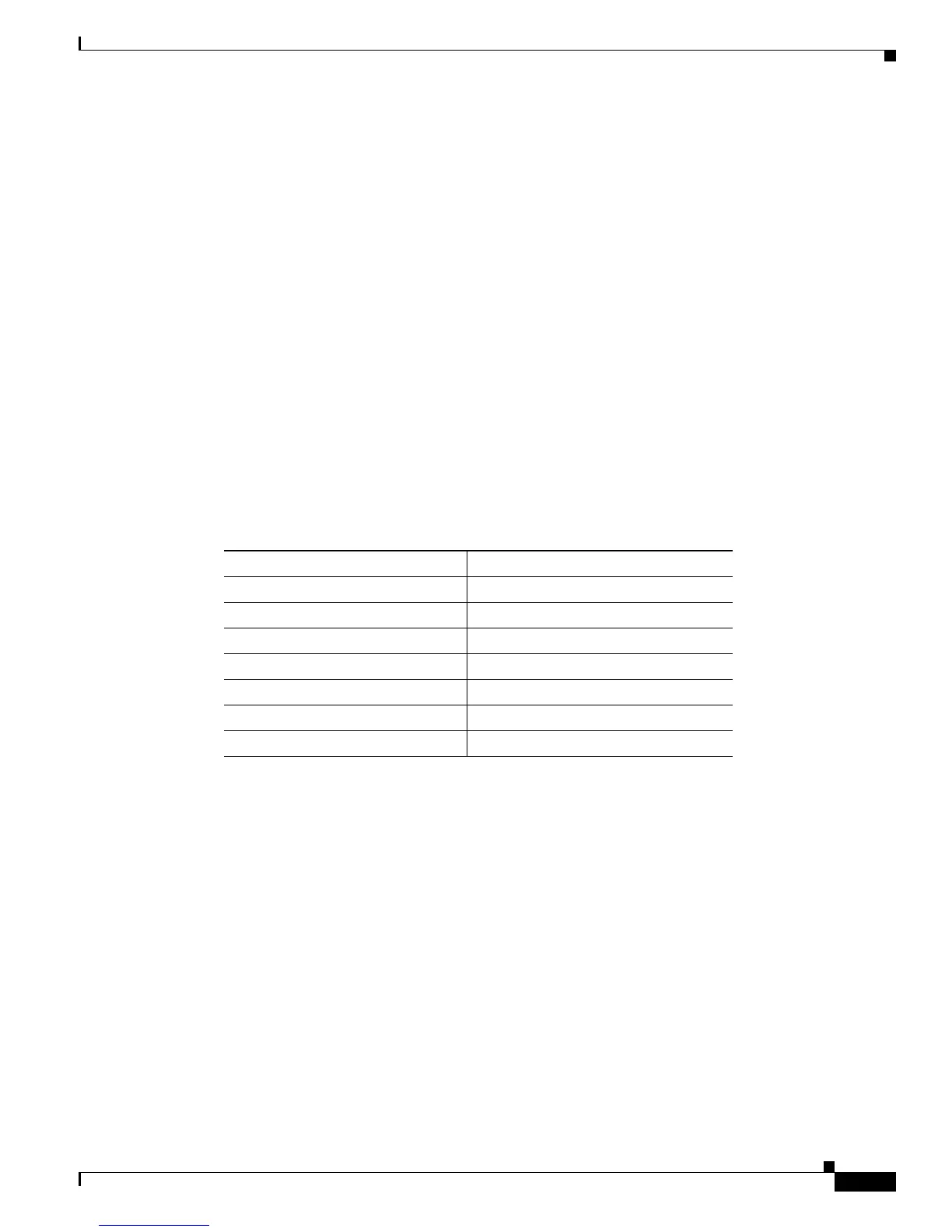
Ta ble 26-5 Default MVR Configuration
Feature Default Setting
MVR Disabled globally and per interface
Multicast addresses None configured
Query response time 0.5 second
Multicast VLAN VLAN 1
Mode Compatible
Interface (per port) default Neither a receiver nor a source port
Immediate Leave Disabled on all ports