26-18
Catalyst 3750-X and 3560-X Switch Software Configuration Guide
OL-21521-01
Chapter 26 Configuring IGMP Snooping and MVR
Understanding Multicast VLAN Registration
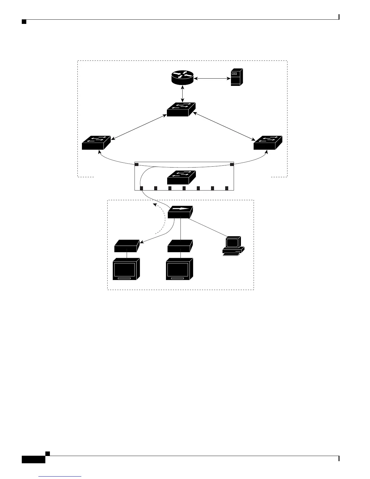
Figure 26-3 Multicast VLAN Registration Example
When a subscriber changes channels or turns off the television, the set-top box sends an IGMP leave
message for the multicast stream. The switch CPU sends a MAC-based general query through the
receiver port VLAN. If there is another set-top box in the VLAN still subscribing to this group, that
set-top box must respond within the maximum response time specified in the query. If the CPU does not
receive a response, it eliminates the receiver port as a forwarding destination for this group.
Without Immediate Leave, when the switch receives an IGM
P leave message from a subscriber on a
receiver port, it sends out an IGMP query on that port and waits for IGMP group membership reports. If
no reports are received in a configured time period, the receiver port is removed from multicast group
membership. With Immediate Leave, an IGMP query is not sent from the receiver port on which the
IGMP leave was received. As soon as the leave message is received, the receiver port is removed from
multicast group membership, which speeds up leave latency. Enable the Immediate-Leave feature only
on receiver ports to which a single receiver device is connected.
MVR eliminates the need to duplicate television-channel multicast traffic for subscribers in each VLAN.
Mult
icast traffic for all channels is only sent around the VLAN trunk once—only on the multicast
VLAN. The IGMP leave and join messages are in the VLAN to which the subscriber port is assigned.
These messages dynamically register for streams of multicast traffic in the multicast VLAN on the
SP1
Multicast
data
Multicast
data
Customer
premises
Multicast VLAN
SP
SP
RP = Receiver Port
SP = Source Port
Note: All source ports belong to
the multicast VLAN.
Hub
TV
data
Set-top boxSet-top box
TV TV
PC
SP
SP
SP
SP
IGMP join
Cisco router
Multicast
server
Switch B
SP2
RP1 RP2 RP3 RP4 RP5 RP6 RP7
101364
Switch A