FC 300 Design Guide
How to Program
parameter is only active in frequency converters
with an integral dynamic brake.
2-12 Braking Energy Limit (kW)
Range:
0.001 - Variable Limit kW
*
kW
Function:
Set the monitoring limit of the braking energy
transmitted to the resistor.
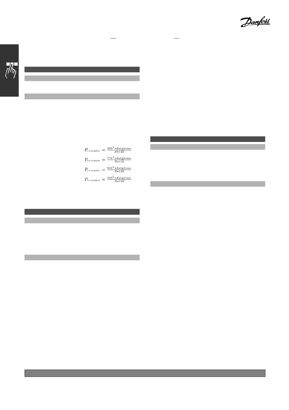
The monitoring limit is a product of the m axim um
duty cycle (120 sec.) and the maximum
power of the brake resistor at that duty cycle.
See the formula below.
For 200 - 240 V units:
For 380 - 480 V units
For 380 - 500 V units
For 575 - 600 V units
This parameter is only active in adjustable frequency
drives with an integral dynamic brake.
2-13 Brake Power Monitoring
Option:
*
Off [0]
Warning [1]
Trip [2]
Wa rning a nd Trip [3]
Function:
This parameter is only active in frequency
converters with an integral dynamic brake.
This parameter enables monitoring of the power
to the brake resistor. The power is calculated
on the basis of the resistanc e (par. 2-11
Brake Resistor (Ohm)), the D C link voltage,
and the resistor duty time.
Select Off [0] if no brake power moni-
toring is required.
Select Warning [1] to activate a warning on the
display when the power transmitted over 120
s exceeds 100% of the monitoring limit (par.
2-12 Brake Power Limit (kW)).
The warning disappears when the transmitted power
falls below 80% of the monitoring limit.
Select Trip [2] to trip the frequency converter
and display an alarm when the calculated power
exceeds 100% of the monitoring limit.
Select Warning and Trip [3] to activate both of the
above, including warning, trip and alarm.
If power m onitoring is set to Off [0 ] or Warning
[1], the brake function rem a ins active, even if the
monitoring limi t is exceeded. This may lead to
thermal overload of the resistor. It is also possible
to generate a warning via a relay/digital outputs.
The measuring accuracy of the power monitoring
depends on the accuracy of the resistance of
the resistor (better than ± 20%).
2-15 Brake Check
Option:
*
Off [0]
Warning [1]
Trip [2]
Trip and Stop [3]
Function:
Select type of test and monitoring function to check
the connection to the brake resistor, or whether a
brake resistor is present, and then display a warning
or an alarm in the event of a fault. The brake
resistor disconnection function is tested during
power-up, and during braking. However the brake
IGBT test is performed when there is no braking. A
warning or trip disconnects the brake function.
The testing sequence is as follows:
1. The DC link ripp le amplitude is measured
for 300 ms without braking.
2. The DC link ripple amplitude is m easured f
or
300 ms with the brake turned on.
3. If the DC link ripple a mplitude whil e braking
is lowe r than the DC link ripple amplitud
e
before braking + 1 %. Brake check failed,
return a warning or ala rm.
4. If the DC l ink ripple amplitude whil
ebraking
is higher than the DC link ripple amplitude
before braking + 1 %. Brake check OK.
Select Off [0] to monitor the brake
resistor and the
brake IGBT for a short-circuit during operation. If
a short-circuit occurs, a warning appears.
*
default setting ()display text []value for use in communication via serial communication port
174
MG.33.B
6.22 - V LT is a registered Danfoss trademark

 Loading...


