FC 300 Design Guide
How to Program
(calculated value). See also par. 14 -25 Trip Delay
at Torque Limit for f urther details.
If a setting in par. 1 -00 to p ar. 1-26 is changed , par.
4-16 is not automatically reset to the default setting.
If par. 4-16 is changed whilst par. 1-00
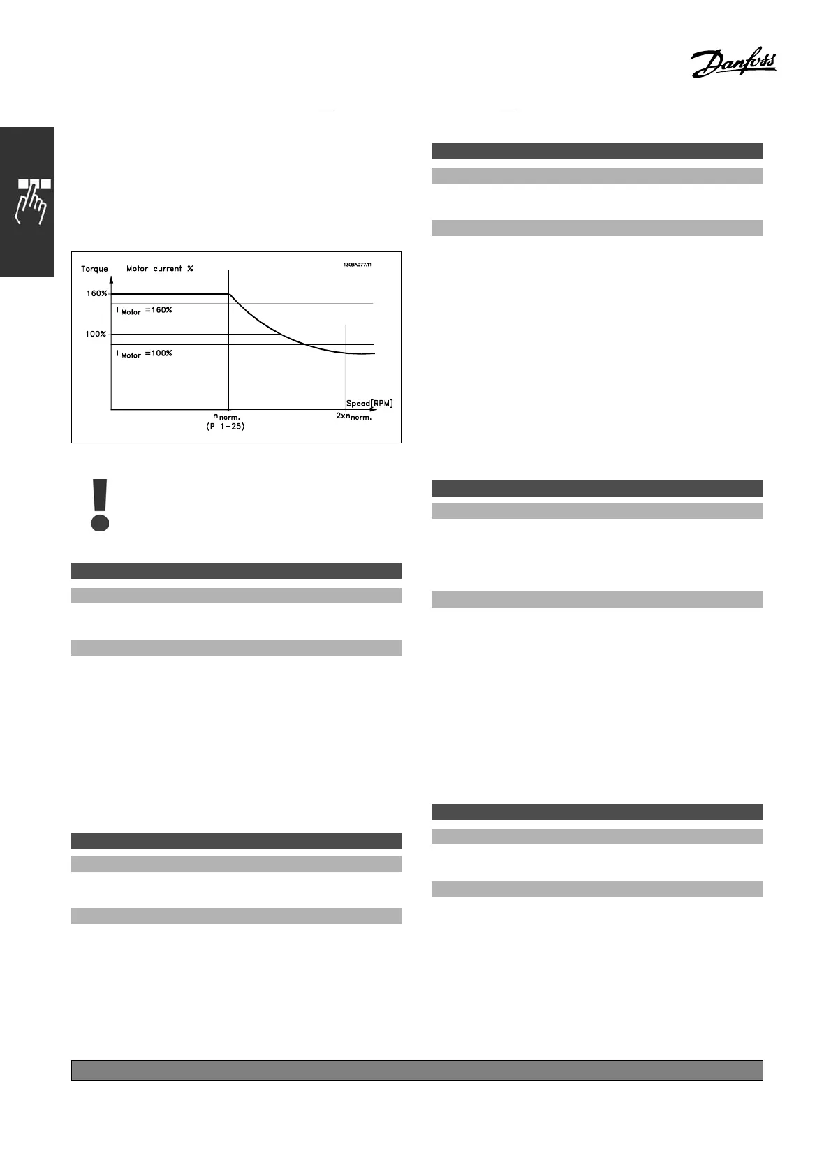
Configuration Mode is set to Speed
open-loop [0], the n par. 1-66 Min Current
at Low Speed will automatically readjust.
4-17 Torque Limit Generator Mode
Range:
0.0-VariableLimit%
*
160.0 %
Function:
Enter t he maximum torque limit for generator mode
operation. The torque limit is active in the speed
range up to and including the rated motor speed
(par. 1-25). See the illus tration for par. 4 -16
Torque Limit Motor Mode,andrefertopar. 14-25
Trip Delay at Torque Limit for further detail s.
If a setting in par. 1 - 00 to par. 1-26 is
changed, par. 4-17 is not automatically reset
to the default settings.
4-18 Curre nt Limit
Range:
0.0-VariableLimit%
*
160.0 %
Function:
Enter the current limit for motor and generator
operation. To protect the motor from reaching the
stalling torque, the default setting is 1.6 x the rated
motor torque (calculated value). If a setting in
par. 1-00 to par. 1-26 is changed, pa r. 4-18 is not
automatically reset to the default setting.
4-19 Max Output Frequency
Range:
0.0 - 1000 .0 Hz
*
132.0 Hz
Function:
Enter the maximum output frequency value.
Par. 4-19 specifies the absolute limit on the
drive output frequency for improved safety
in app lications where accidental overspeeding
must be avoided. This abso lute lim it applies
to all configurations and is independent of the
setting in par. 1-00. This pa rameter cannot be
adjusted while the m otor is running.
" 4-3* Motor Feedback Monitoring
This parameter group includes settings f or
monitoring and handling of motor feedback devices
such as encoders and resolvers.
4-30 M otor Feedback Loss Function
Option:
Disabled [0]
Warning [1]
*
Trip [2]
Function:
Select the adjustable frequency drive reaction
upon detecting a feedback fault, i.e., when the
feedback signal differs from the output speed
more tha n specified in par. 4-31 Motor Feedback
Speed Error duringthetimesetinpar. 4-32
Motor Feedback Loss Timeout.
Select Disabled [0] if no action is required.
Select Warning [1] to issue a warning only. The
adjustable frequency drive will continue operation.
Select Trip [2] to trip the adjustable frequency drive.
4-31 Motor Feedback Speed Error
Range:
1-600 RPM
*
300 RPM
Function:
Enter the maximum permissible tracking
error between the calculated and the a ctual
mechanical shaft output speed.
*
default setting ()display text []value for use in communication via serial communication port
188
MG.33.B
6.22 - V LT is a registered Danfoss trademark

 Loading...


