FC 300 Design Guide
FC 300 Selection
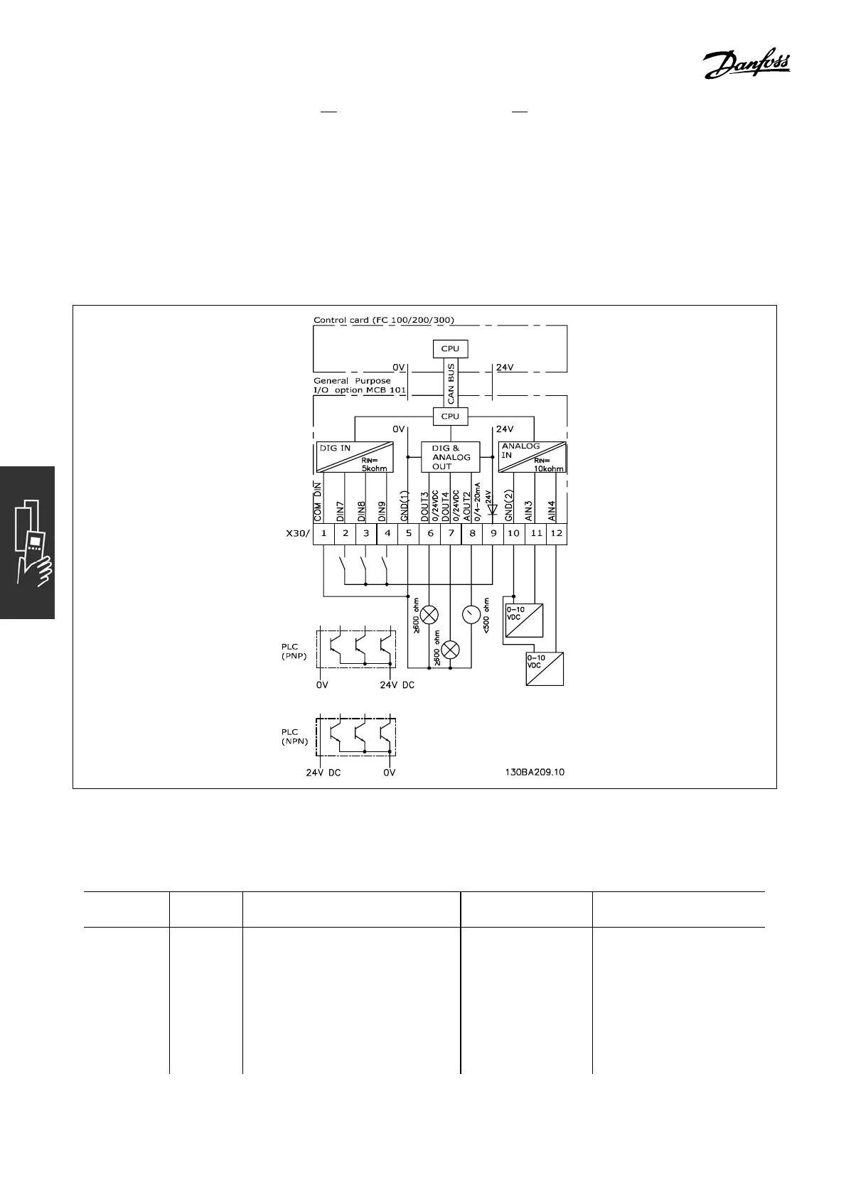
" Galvanic Isolation in the MCB 101
Digital/analog inputs are galvanically isolated from other inputs/outputs on the MCB 101 and in the
control card of the drive. Digital/analog outputs in the MCB 101 are galvanically isolated from other
inputs/outputs on the MCB 101, but not from the ones on the control card of the drive.
If digital inputs 7, 8 or 9 are to be switched using the internal 24 V power supply (terminal 9), the
connection between terminal 1 and 5 illustrated in the drawing has to be established.
Principle Diagram
"
Digital inputs - Terminal X30/1-4
Parameters for set-up: 5-16, 5-17 and 5-18
Number of
digital inputs
Voltage
level
Voltage levels Input impedance Max. load
3 0-24 V DC PNP type:
Common = 0 V
Logic “0”: Input < 5 V DC
Logic “0”: Input > 10 V DC
NPN type:
Common = 24 V
Logic “0”: Input > 19 V DC
Logic “0”: Input < 14 V DC
Approx. 5 k ohm ± 28 V continuous
±37Vinminimum10sec.
74
MG.33.B6.22 - VLT is a registered Danfoss trademark