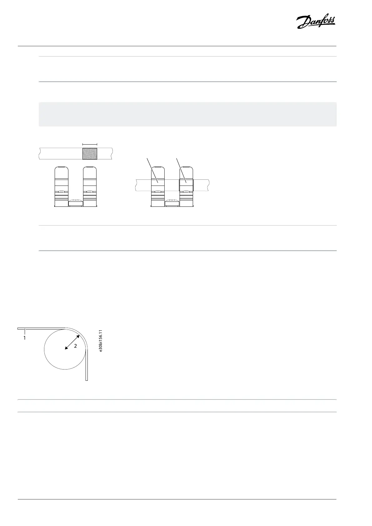
1 Control cable 2 Cable clamp
3 Grounding plates
2. Strip the control cables. Attach the control cables to the cable clamps on the suitable grounding plate.
The lower part of the cable clamp fixes the cable to the plate and provides strain relief. The upper part provides ~360°
grounding for the cable shield.
Figure 111: Stripping the Cable and Using the Grounding Plates
1 Stripping length, 10 mm (0.4 in) 2 Strain relief
3 Grounding
8.16 Connecting the Control Panel
1. Connect the control panel to the terminal X9 in the modular control unit with a panel cable adapter.
8.17 Fiber Cable Requirements
The required fiber cable type is LC duplex cable assembly 0.5NA SI-POF.
The installation temperature of the fiber cable is -40...+85 °C (-40...+185 °F). The minimum bending radius is 25 mm (1.0 in).
Figure 112: Bending Radius of the Fiber Cables
1 Cable 2 Bending radius (25 mm, 1.0 in)
112 | Danfoss Drives Oy © 2024.03 AJ475942178716en-000101 / 172K2848A
Design Guide | iC7 Series Liquid-cooled System Modules
 Loading...


