Design Guide | iC7 Series Liquid-cooled System Modules
Table 15: Definitions of the Indicator Lights on the Control Board (continued)
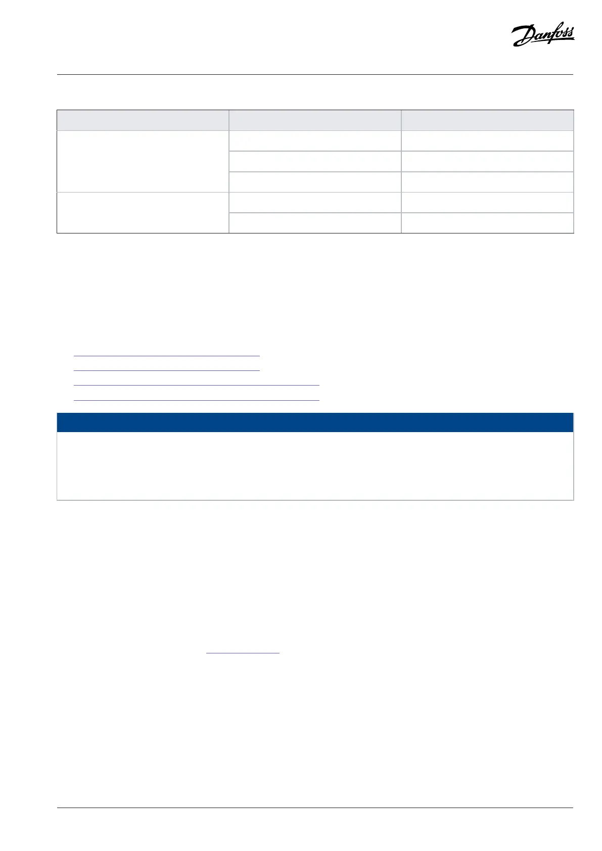
Indicator name Function (color) Description
Off No link
On (green) Link OK, no data
X0 link activity
Blinking (green) Link OK, data communication
Off No link or 10 Mbps linkX0 link speed
On (orange) 100 Mbps link
For the description of the fieldbus indicators (ST, X1, X2), see the relevant application guide.
7.12 Installation in an IT System
If the mains is impedance-grounded (IT), the AC drive must have the EMC protection level C4. If the drive has the EMC protection level
C3, it is necessary to change it to C4. To change the EMC protection level of the AC drive from C3 to C4, disconnect the LC Filter ground
capacitor. See instructions:
l 7.12.1 Changing the EMC Protection Level, AR10L
l 7.12.2 Changing the EMC Protection Level, AR12L
l 7.12.3 Changing the EMC Protection Level, LC Filter, OF7Z1, 380 A
l 7.12.4 Changing the EMC Protection Level, LC Filter, OF7Z1, 760 A
NOTICE
DAMAGE TO THE AC DRIVE FROM INCORRECT EMC LEVEL
The EMC level requirements for the AC drive depend on the installation environment. An incorrect EMC level can damage the
drive.
l Before connecting the AC drive to the mains, make sure that the EMC level of the AC drive is correct for the mains.
In a non-dedicated IT system, it is recommended to leave the ground capacitors connected in each AFE and GC to limit conducted
high-frequency disturbances between devices across the system. A non-dedicated IT system is defined here as a network where several
separate DC links are fed from the same AC supply.
If the ground capacitors are connected, continuous operation during an IT ground fault is not allowed, because a large fault current is
going through the capacitors.
In common DC bus installations supplied through a dedicated transformer or an NFE, and with common-mode voltage-sensitive energy
storages or equipment connected to the DC bus, it is recommended to have ground capacitors on the DC bus side (DC+ to PE and DC- to
PE) to balance the DC bus voltage against ground. In this case, the AC side ground capacitors should be disconnected. This can affect the
installation altitude, see more details in 10.8 Technical Data. The ground capacitors should be sufficiently larger than the system parasitic
capacitance to ground to be effective in limiting the common-mode voltage peaks.
As a rule-of-thumb:
l 10 x system parasitic capacitance ~ 100 V common-mode voltage to ground
l 100 x system parasitic capacitance ~ 10 V common-mode voltage to ground
Continuous operation during ground fault when DC side ground capacitors are connected is not allowed due to potentially large fault
currents.
Danfoss Drives Oy © 2024.03 AJ475942178716en-000101 / 172K2848A | 75
 Loading...


