EasyManua.ls Logo

Danfoss iC7 Series

Danfoss iC7 Series
224 pages
To Next Page IconTo Next Page
To Previous Page IconTo Previous Page
Loading...
Design Guide | iC7 Series Liquid-cooled System Modules
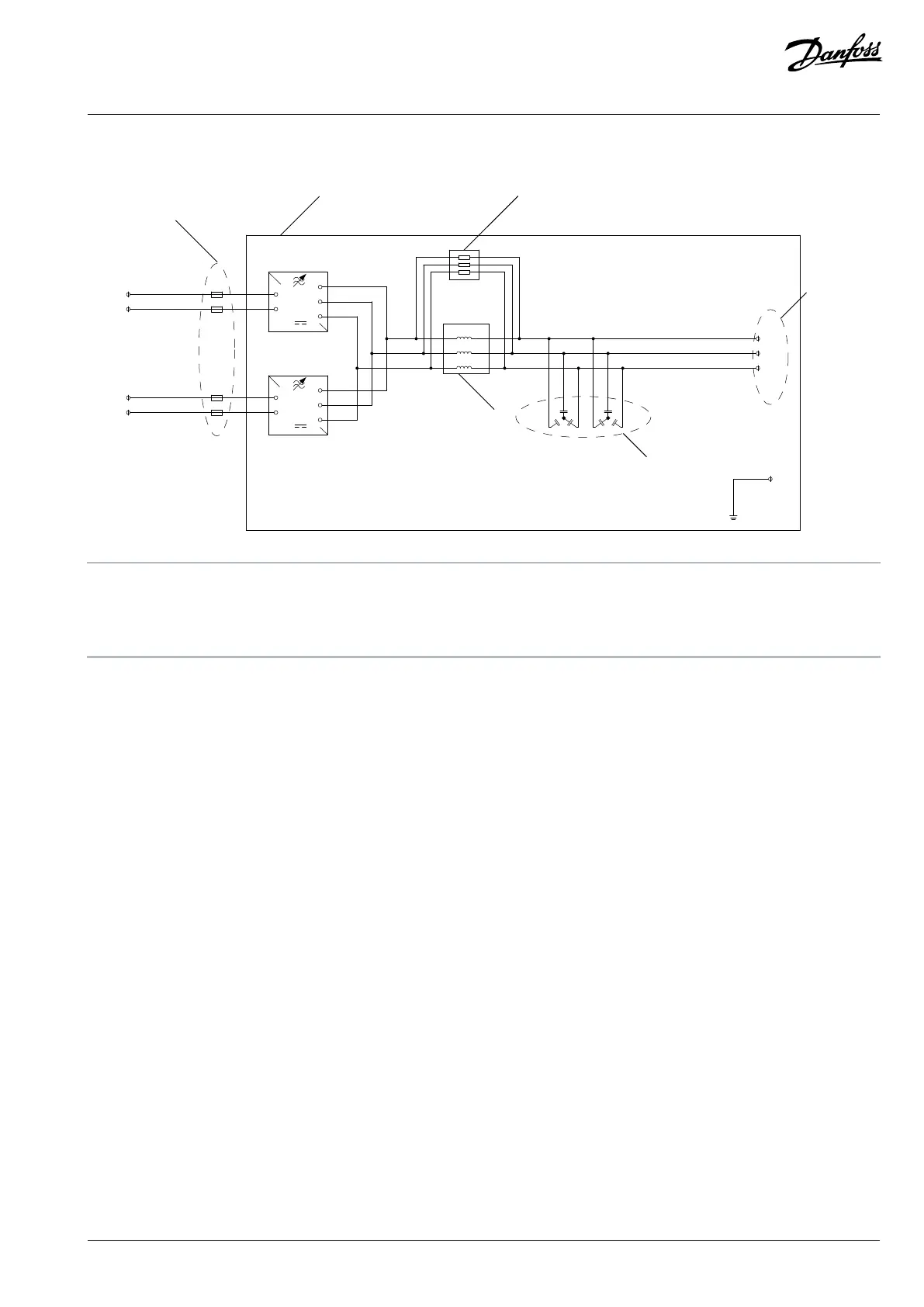
10.3.4 Wiring Diagram, INU, IR12L
DC-
DC+
W
V
U
DC-
DC+
W
V
U
U'
V'
W'
U
V
W
INU
INU
V/T2
U/T1
W/T3
DC+
DC-
DC+
DC-
PE
1
2 3
5
4
6
e30bg430.10
1 DC fuses, loose option 2 Inverter module IR12L
3 Damping resistors 4 Output terminals
5 dU/dt Filter capacitors 6 dU/dt Filter choke
Figure 161: Wiring Diagram, IR12L
Danfoss Drives Oy © 2024.03 AJ475942178716en-000101 / 172K2848A | 159

Table of Contents

Other manuals for Danfoss iC7 Series

Related product manuals