8.6 Definitions of the Indicator Lights on the Star Coupler Board
Table 25: Definitions of the Indicator Lights on the Star Coupler Board
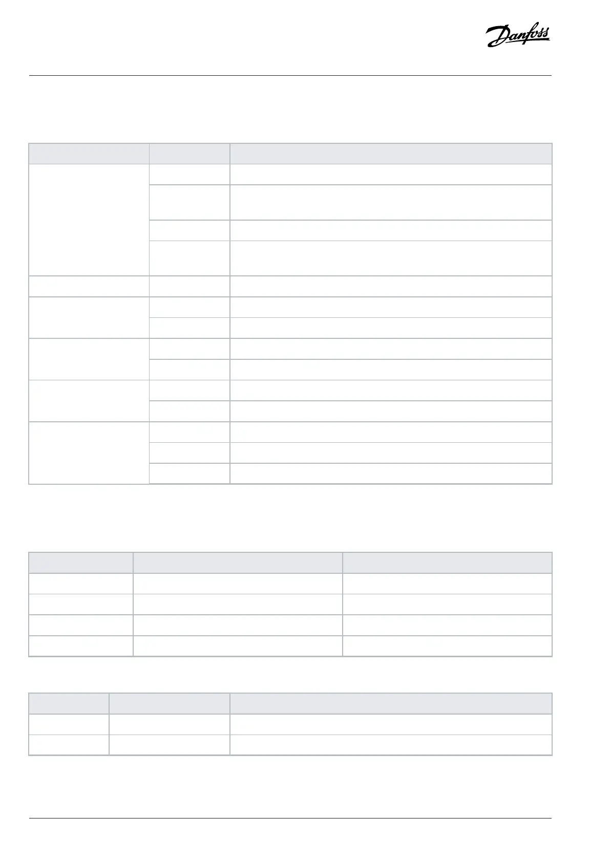
Indicator name Function (color) Description
Off During booting, until the software configuration is executed.
Blinking 10 Hz
(green)
Software updating.
On (green) Board configuration succeeded and all port communication works as intended.
Configuration status
On (red) Board configuration failed or any port communication failed on startup or during
run.
24 V power status On (white) Star coupler board is powered.
Off No link established.Power unit link status
(X301–X316)
On (green) Link established.
Off No link established.Control link status
On (green) Link established.
Off No link or 10 Mbps linkEthernet speed
On (orange) 100 Mbps link
Off No link
On (green) Link OK, no data
Ethernet link activity
Blinking (green) Link OK, data communication
8.7 Star Coupler Board Connections
Table 26: Star Coupler Board Connections
Terminal Function Connector type
X7 Ethernet port RJ45
X65 24 V DC supply 2 x spring force connector 2.5 mm
2
X90 Fiber optic link to control board LC-duplex
X301–X316 Fiber optic link to power unit LC-duplex
Table 27: 24 V DC Supply Signals (X65)
Terminal Function Description
61 +24 V external input External +24 V DC star coupler supply, maximum 10 A. Must be fuse-protected.
62 GND Power supply ground
100 | Danfoss Drives Oy © 2024.03 AJ475942178716en-000101 / 172K2848A
Design Guide | iC7 Series Liquid-cooled System Modules
 Loading...


