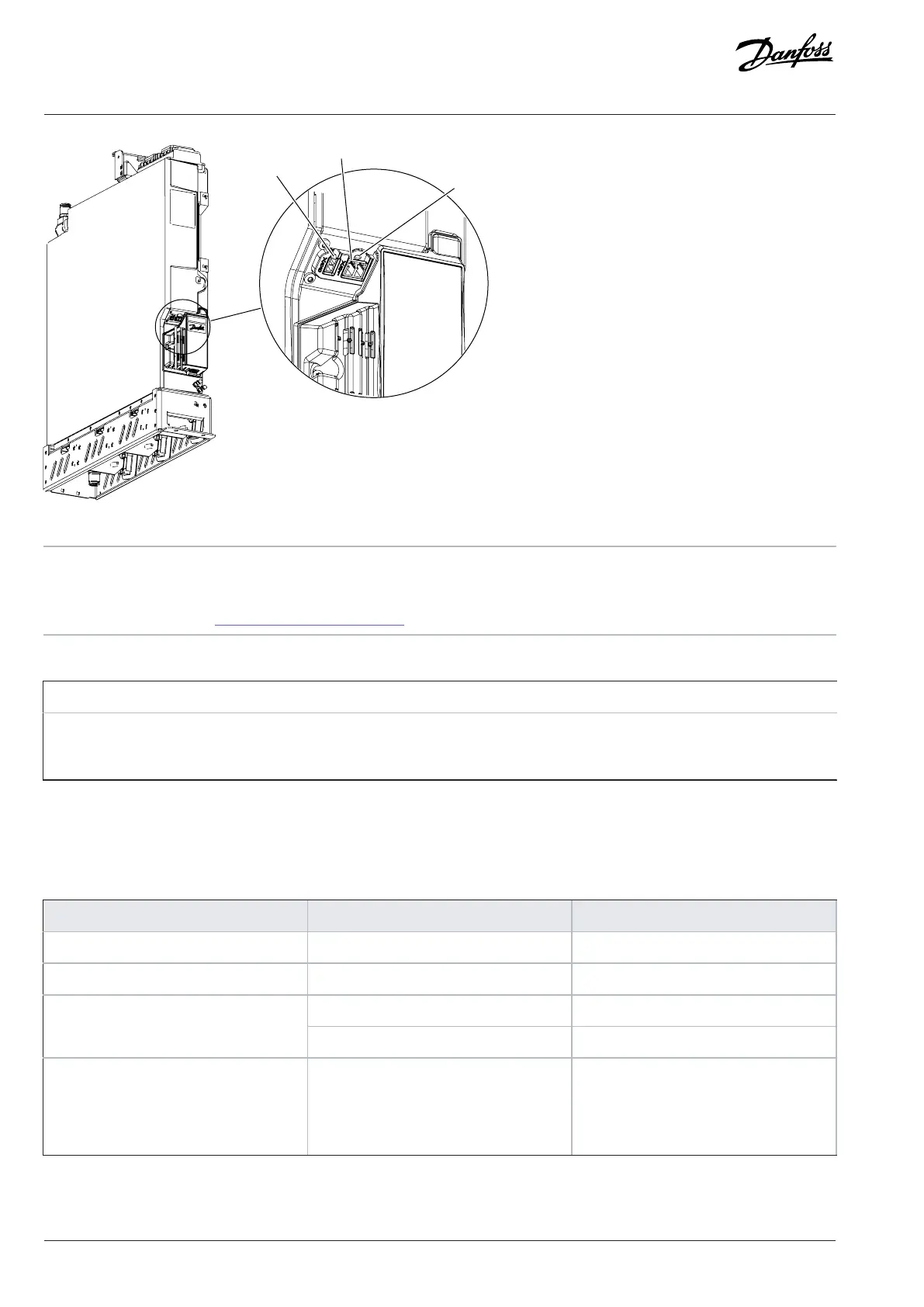
Figure 69: Auxiliary Power Connection for INU
1 Auxiliary +24 V DC connection (X66) 2 Optical fiber connection to control unit or star coupler
board (X81)
3
Status indicator (See 7.11.1 Indicator Light Definitions.)
(1)
1) The status indicator is not implemented yet.
Pin number in X66 Voltage
1
23–26 V DC, 10 W continuous, 25 W peak power
(1)
2 0 V DC
1) Cabling must be sufficient for supplying the 25 W peak power.
7.11.1 Indicator Light Definitions
Table 15: Definitions of the Indicator Lights on the Control Board
Indicator name Function (color) Description
Fault On (red) Fault active
Warn On (yellow) Warning active
On (white) Ready for operationReady
Blinking 1 Hz (white) Power on, not ready
Fault+Warn+Ready Blinking (red+yellow+white) Signaling from an external application.
Can be used for identifying where the ex-
ternal application is wirelessly connected
to.
74 | Danfoss Drives Oy © 2024.03 AJ475942178716en-000101 / 172K2848A
Design Guide | iC7 Series Liquid-cooled System Modules
 Loading...


